www.bvmsystems.co.uk
sales@bvmsystems.co.uk
40-0287-12
- 3 -
1 GENERAL
The purpose of a PQSensor™ is to equip a standard CVT with an interface that enables it to
be used to make accurate measurements of harmonic levels and transients on h.v. power net-
works.
The PQSensor™ consists of three separate components
The Measurement Unit (MU)
The Signal Conditioning Module (SCM)
The Interconnecting Cable
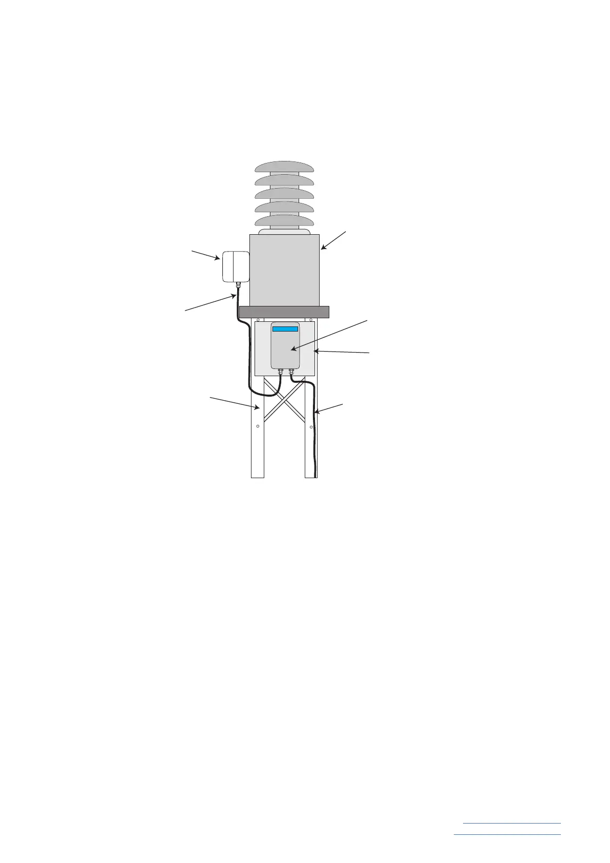
An example of a PQSensor™ installation is shown in Figure 1.
When installing the SCM box it is essential to ensure that it is positioned below the safety clear-
ance height that will permit it to be accessed while the CVT is in service. The ideal mounting
height for the PQSensor™ SCM is between 0.9m and 1.5m above ground level and for future
access and serviceability after commissioning it should always be mounted in this area.
1.1 The Measurement Unit
The Measurement Unit (MU) is a 66mm (w) x 66mm (d) x 81mm (h) module that contains the
transducers that acquire the signals used to produce its high accuracy wide band voltage out-
put. There are two sets of inputs, HCCT and LCCT together with their associated outputs. The
PQSensor™
CVT Electromagnetic Unit
Tank
CVT Secondary
Terminal Box
PQSensor™ Signal
Conditioning Module (SCM)
PQSensor™Mounting Plate
PQSensor™
Interconnecting
Cable
CVT Support
Structure
PQSensor™ - Installation
PQSensor™
Supply and
Output Signal Wiring
Figure 1
 Loading...