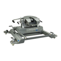
PREPARING TO INSTALL
INSTALL SLIDER BASE
The Companion base will mount to four attachment
points in the truck bed. Remove any debris and/or
obstructions from the truck bed, this includes any
plastic caps which may be over the attachment points.
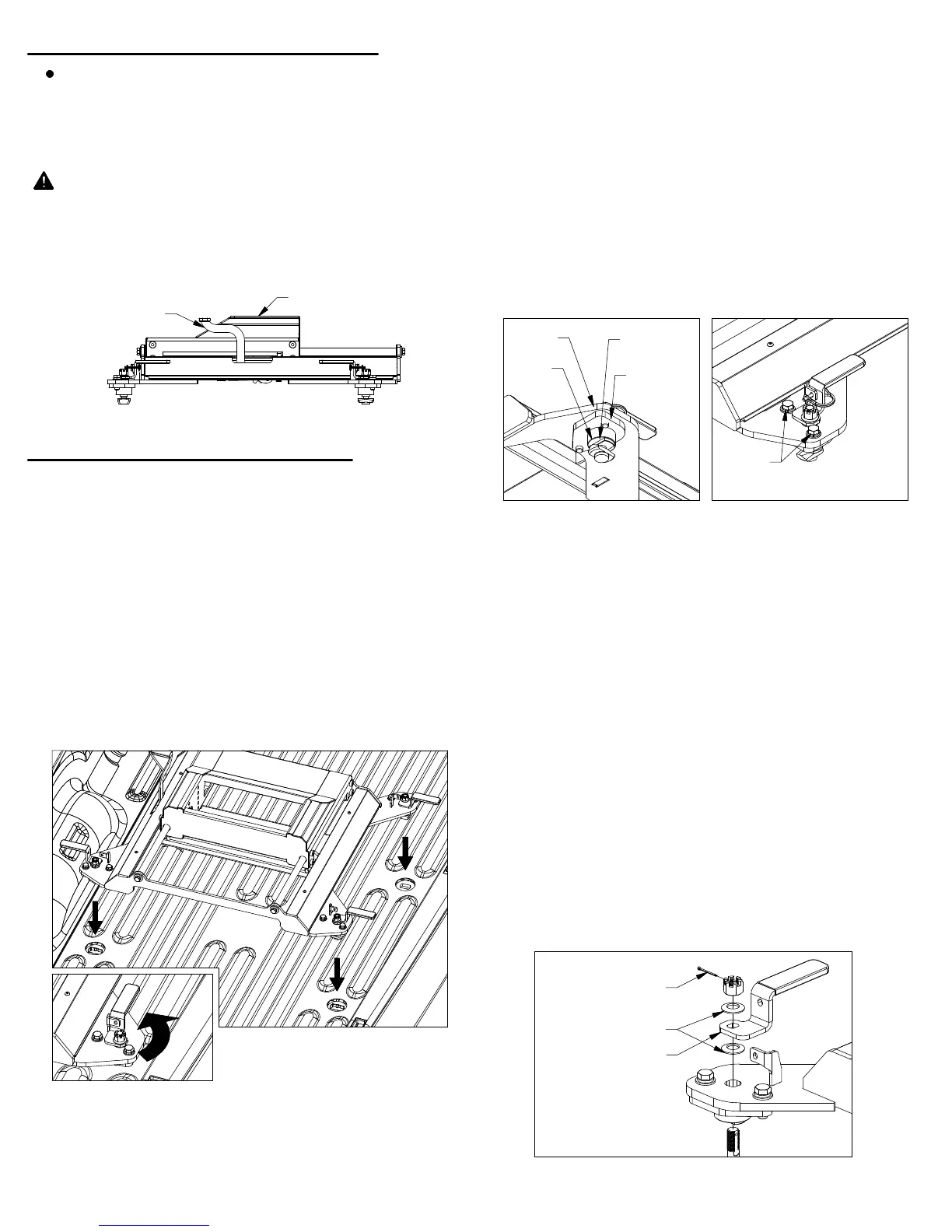
Remove the latch pins from each side of the base and
rotate the handles out, see Figure B1. Place the base
over the attachment points and carefully lower it until
the latch cams pass through the floor and the base
rests flat against the top of the attachment points.
Prepare to adjust latch tension. Once the base is
in place, remove the cotter pins from each of the four
castle nuts. Engage the cams with each attachment
point by turning the latch handles back to their locked
position, see Figure B2. If a handle will not turn easily,
loosen the castle nut until the cam will freely turn and
engage the attachment point.
Adjust the tension in the latch handle, for parts list
and visual guide refer to Figures B5 and B6.
With the handles in the latched position, tighten the
castle nut until snug to increase the tension on the
latch. Rotate the latch handle open and closed.
Tighten the castle nut slightly and rotate the handle
open and closed again. Repeat this process until you
feel the cam engage the attachment point while
closing the handle. The handle is set at the proper
tension when there is friction between the cam and
attachment point but the handle can still be closed by
hand without bumping, tapping, or otherwise forcing
the handle closed.
1.
Adjustment instructions continued on next page.
3.
WARNING:
The latch cams and handles must be
adjusted to fit the tow vehicle. Failure to properly
adjust the cams and handles may result in property
damage and/or personal injury.
Each leg of the Companion base has an adjustable pilot
assembly which is attached to the foot with two 1/2" cap
screws, as shown in Figure B4. To adjust the pilot
assemblies that do not fit into the attachment points,
loosen both the 1/2" cap screws so the pilot assembly
can move freely, see Figure B4. Set the base over the
attachment points and adjust the pilot assemblies until
the pilot keys pass through the slot in the attachment
points and the pilot shoulders rest flat against the top of
the attachment points. When all the pilot assemblies
are aligned and inside the attachment points, push the
base towards the cab and use a tape measure to verify
that the base is approximately square with the truck
bed. Tighten any loose cap screws to 80 ft−lbs.
2.
Remove any debris and/or obstructions from the truck
bed, this includes any plastic caps which may be over
the attachment points. It may also be necessary to
remove the plastic grommets from around the mounting
points in order to fully seat the base down to the truck.
WARNING: Whenever the slider base is being
moved, the slider handle must be in the locked
position, and the carriage must be unable to slide,
see Figure A1. Failure to ensure that the handle is in
the locked position can lead to property damage, or
serious injury.
PAGE 2 of 5
IMPORTANT: The attachment points may differ from
truck to truck. If the pilots fit into the trucks
attachment points you may skip Step 2 and continue
with Step 3. If the Companion base does not fit into
the attachment points proceed to Step 2.
4.
Figure A1: View of driver side of Slider Base.
Figure B1:
View of unlatched base.
Figure B2: View of closed latch handle.
Figure B3: View under base foot
Figure B4: View of base foot
Figure B5: List of latch parts.
SLIDER HANDLE
IN LOCKED POSITION
SLIDER CARRIAGE
1/2" CAP
SCREW
PILOT
ASSEMBLY
BASE
FOOT
PILOT
KEY
PILOT
SHOULDER
COTTER PIN
LATCH HANDLE
FLAT WASHER
 Loading...