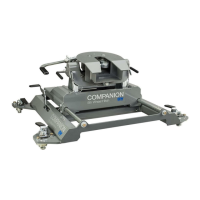
Figure D3: Base view.
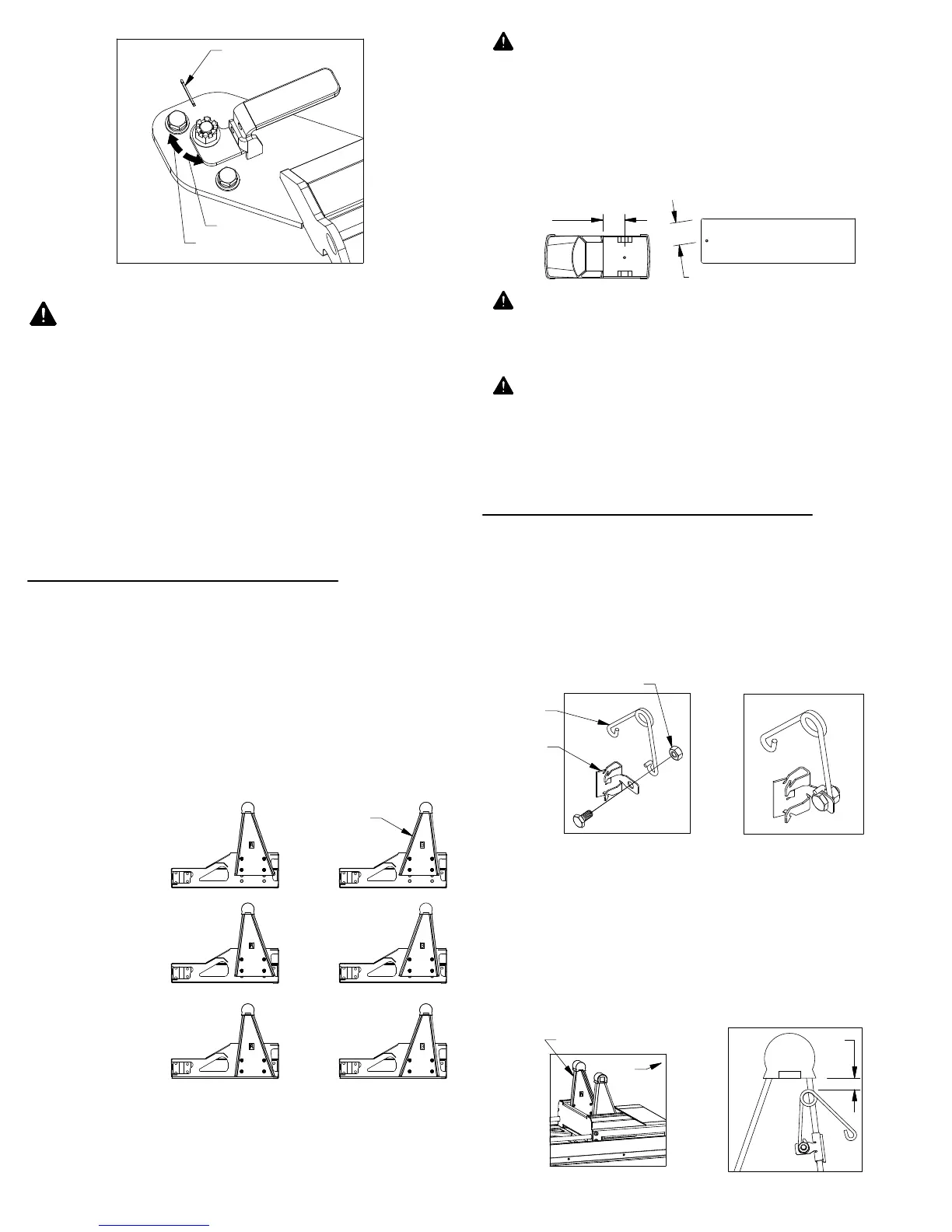
Figure C1: Cut away view of slider carriage arm positions.
WARNING: Check the clearance between the truck
cab and the trailer in both the towing position and the
maneuvering position. Compare the measurement
taken from the center of the Slider Coupler to the cab,
to the measurement taken from the center of the king
pin to the farthest forward corner point of the trailer.
These measurements will allow you to see how much
clearance you will have between the cab and the
trailer while towing and turning.
WARNING: Check the clearance between the bed
side and the underside of the front of the trailer and to
allow adequate clearance for the pitch and roll of the
trailer while towing.
WARNING: Parts of the trailer may strike the tailgate
when sliding the companion rearward. Check the
clearance between the tailgate and trailer components
such as the trailer tongue or pin box. Failure to check
clearance may cause property damage.
INSTALL PIVOT ARMS
Mount the pivot arms using one of the six different
locations illustrated in Figure C1. These six locations
allow flexibility in coupler height and distance from the
cab. Choose a location so that your trailer will be as
level as possible and have adequate turning clearance
while in the towing position (with the slider in the
forward position). See warnings after step 2.
With the base firmly held down and each latch handle
closed, replace the latch pins removed in Step 1.
NOTICE: Verify latch tension each time the
Companion base is placed in a truck, and periodically
before towing.
Locate the 1/4" cap screw and nut, along with the wire
tension spring and mounting clip. Pass the 1/4" cap
screw through the mounting clip and the wire spring,
as shown in Figure D1. Thread the 1/4" lock nut onto
the 1/4" cap screw. Tighten the lock nut just enough
that the spring will stay in place but will still be able to
rotate around the bolt if needed, see Figure D2.
INSTALL LEVELING KIT
Locate the flange which will be closest to the truck cab
on the driver side pivot arm, see Figure D3. The clip
should be placed so that when the spring’s coil is in
line with the edge of the arm there will be 1/2" of
clearance between the bottom of the rubber bumper
and the top of the spring, see Figure D4. Drive the
clip securely onto the flange with a hammer.
2.
1.
With the flat side of the pivot arm flat against the bolt
plate in the slider base, install four 1/2" x 2" bolts and
four 1/2" split lock washers for each arm. Torque each
bolt to 80 ft−lbs.
2.
1.
PAGE 3 of 5
5.
WARNING:
Setting latch handle tension so that
excessive force is required to close the latch handles
may result in property damage and/or personal injury.
Figure D2:
Assembled leveling kit.
Figure D1:
Leveling kit parts.
Figure D4: Driver side pivot arm.
BED FLOOR TO TOP OF
COUPLER
KINGPIN 2"
IN FRONT OF AXLE
POSITION CLOSEST TO CAB
KINGPIN OVER AXLE
POSITION FARTHEST FROM
CAB (ARMS REVERSED)
HIGHEST
POSITION
(19")
MIDDLE
POSITION
(18")
LOWEST
POSITION
(17")
Figure B6: View of base leg.
CENTER OF
COUPLER
TO CAB
KINGPIN TO EDGE OF TRAILER
WIRE
SPRING
1/4" LOCK NUT
MOUNTING
CLIP
1/2"
DRIVER SIDE PIVOT ARM
CAB
PIVOT ARM
COTTER PIN
LOOSEN
TIGHTEN
 Loading...