Installation Instructions
1. Place the oxidizer tank where you want to install the unit making sure the unit is level and on
a rm base.
2. During cold weather, the installer should warm the valve to room temperature before
operating.
3. All plumbing must be done in accordance with local plumbing codes. The pipe size for
residential drain line should be a minimum of 1/2” (13 mm). Backwash ow rates in excess of
7 gpm (26.4 L/pm) or length in excess of 20’ (6 m) require 3/4” (19 mm) drain line. Commercial
drain lines should be the same size as the drain line ow control. Due to the release of
the air during regeneration, the drain line must be secured at the end, and anchored
throughout the run.
4. The check valve supplied with the valve must be installed at the valve inlet to prevent the
pressurized air head in the oxidizer tank from venting backwards up the feed water plumbing.
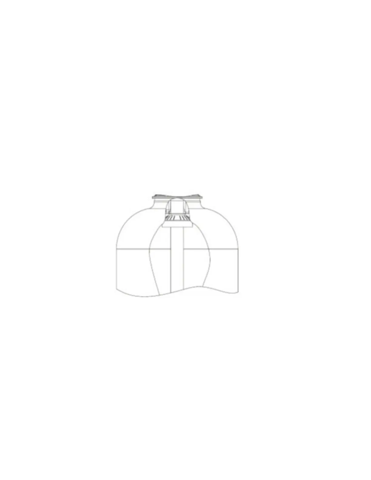
5. If not factory installed assemble the deflector to the distributor tube.
Deflector Installation:
Put a thin layer of silicone lube around inside diameter of the deflector. Slowly slide the deflector
over the distributor tube down about 1”. When threading the AIO valve to the tank, the bottom
of the threads will slide the deector down. As shown above.
6. Lubricate the distributor O-ring seal and tank O-ring seal. Place the main control valve on
tank.
Note: Only use silicone lubricant.
7. Solder joints near the drain must be done prior to connecting the Drain Line Flow Control
tting (DLFC). Leave at least 6” (15 cm) between the DLFC and solder joints when soldering
pipes that are connected on the DLFC. Failure to do this could cause interior damage to the
DLFC.
8. Teon® tape is the only sealant to be used on the drain tting. Do not use pipe dope or
other compounds as they contain petrochemical elements and will attack the drain housing
and cause failure.
2
 Loading...