11
4 AdJ
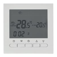
Room
temperature
adjust
(Calibration)
-5ºc – 5ºC
0.0ºC
5 FrE
Anti-freezing
function
00: Anti-freezing function shutdown
01: Anti-freezing function enabled
00
6 LOC Lock function
00: Lock disabled
01: Half lock
02: Full lock
00
7 FAC Factory default
08: Maintaining current settings
00: Restore Factory default
08
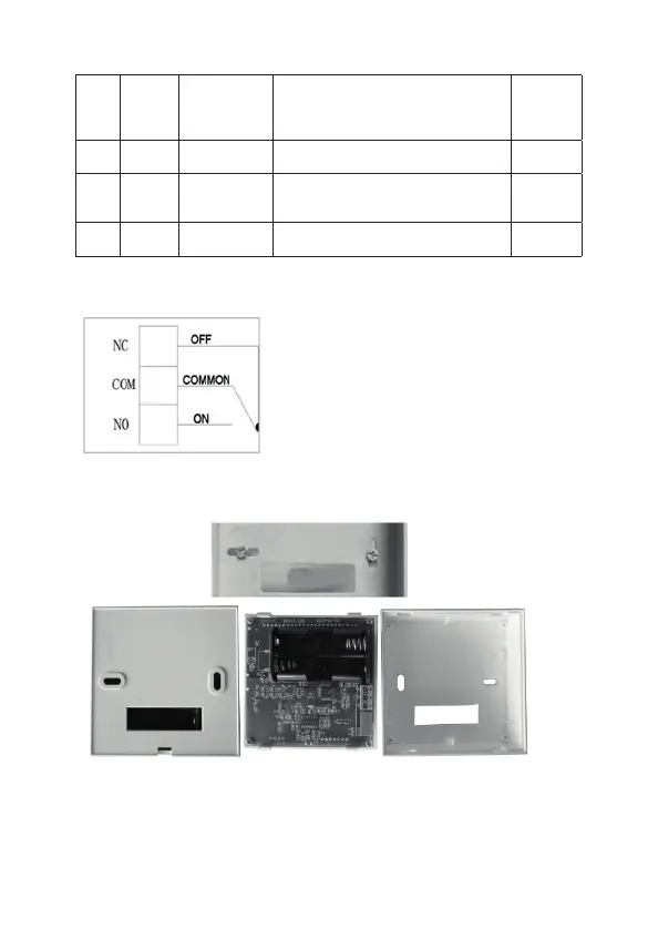
Connection diagram
NC: Normally close contact
COM: Common terminal
NO: Normally open contact
Installation
1. After open upper panel and bottom panel, x the bottom panel on the wall using two screws,
entering the required wires through hole of the bottom panel. It is recommended that the wires
have a length of 20 cm in order to facilitate the connection.
2. Install two AA batteries and connect the wires on input terminals.
3. Finally, close bottom panel and upper panel.
 Loading...