EasyManua.ls Logo

C-TEC FP4E - User Manual

C-TEC FP4E
4 pages
Print Icon
To Next Page IconTo Next Page
Loading...
FP4E 4 Zone Economy Fire Alarm Control Panel (Part No. FF384-3)
Installation Instructions
FIRE ALARM
ancillaries
1 of 4
Approved Document No. DFU0384011 Rev 2 Draft 4
THIS EQUIPMENT MUST ONLY BE INSTALLED AND MAINTAINED BY A SUITABLY SKILLED AND TECHNICALLY
C
OMPETENT PERSON. THIS EQUIPMENT IS A PIECE OF CLASS 1 EQUIPMENT AND MUST BE EARTHED
.
DO NOT CHANGE ANY PANEL CONNECTIONS WITH THE PANEL’S POWER APPLIED (MAINS OR BATTERY POWER).
DETECTOR
DETECTOR
CALL POINT
CPR
CALL POINT
CPR
DO NOT SPUR -
CIRCUIT NOT MONITORED!
-
+
PANEL ZONE
TERMINALS
DETECTOR DETECTOR
CPR
CALL POINT
CPR
+
-
-+
EMU PANEL MODULE
BF378 or
BF378M
ELECTRONIC MONITORING UNIT (EMU)
CALL POINT
Fig 5
SOUNDERS
+
+
EOLR
+ +
+ +
DO NOT make off
more than 2 circuits
in the panel
EOLR
SOUNDERS
EOLR
EOLR = End of Line Resistor (6k8Ω, 0.25W) - supplied
CPR = Call Point Resistor (470 - 680Ω, 0.5W) - supplied with call point
PANEL ZONE
TERMINALS
PANEL SOUNDER
TERMINALS
TYPICAL ZONE CIRCUIT - Call points wired before detectors
- Detector base diodes not needed.
TYPICAL ZONE CIRCUIT - With mixed order call points and detectors
- Detector bases fitted with continuity diodes and negative connection linked out.
TYPICAL SOUNDER CIRCUITS
Only use polarised sounders!
Remove EOLR from
terminal block and
fit to last detector.
DO NOT SPUR -
CIRCUIT NOT MONITORED!
Remove EOLR from
terminal block(s) and
fit to last sounder.
+
+
-
-
5
6
7
8
INSTALLATION PROCEDURE
All cables must be installed in accordance with all applicable national, regional or local standards. In the UK this is BS 7671 IEE
Wiring Regulations and BS 5839-1, Fire detection and alarm systems for buildings: Code of practice for system design, installation
and maintenance. Fire resistant, screened cable should be used throughout the installation and Mains wiring should be
segregated from extra low voltage field wiring.
For PERMANENTLY CONNECTED equipment, a readily accessible disconnect device shall
be incorporated external to the equipment.
The general requirement for the Mains supply to the panel is fixed wiring, using 3 core
cable, (no less than 1mm
2
and no more than 2.5mm
2
), or a suitable three conductor
system fed from an isolating switched fused spur, fused at 3A. The Mains supply must
be exclusive to the panel.
HINT. As an alternative to a switched
fused spur, a double pole isolating
device (B) may be used in the Mains
feed from the Main Distribution
Board (A) to the panel (C), providing
it meets the appropriate wiring
regulations – see Fig 1.
Remove the panel’s lid (disconnect attached loom connector).
Fit the panel’s back box securely to a wall using the mounting holes provided and
suitable screw fixings. Remove required number of knockouts and fill holes with good
quality cable glands – see Fig 2.
Gland field cables and terminate all screens to the panel.
CAUTION: DO NOT use an insulation tester (Megger) with any electronic devices
connected as the test voltage will totally destroy the devices.
Test field cables and ensure they are fault-free, i.e. check continuity of cable runs
(including screens).
Connect external Mains cable to the panel’s fused Mains terminal block (with Mains
isolated) – see Fig 2.
CAUTION: RISK OF EXPLOSION IF BATTERY IS REPLACED BY AN INCORRECT TYPE.
DISPOSE OF USED BATTERIES ACCORDING TO THE INSTRUCTIONS.
Also, if the battery leads are connected in reverse, the battery fuse (F1) will blow
which may damage the panel and invalidate the warranty.
Position and connect the panel’s two internal 12V sealed lead acid batteries (with
battery supply isolated) – see Fig 3 & Fig 4.
Connect zone circuits to the panel – see Fig 5.
Connect sounder circuits to the panel – see Fig 5.
Connect ancillary connections to the panel.
Refit the panel’s lid (re-connect loom connector).
Apply Mains and battery supply to power up the panel.
The panel should be in normal mode. If not, investigate and rectify any faults
indicated on the panel.
Finally, test the panel – see pages 2 & 3.
Shorting Link
(supplied)
+
12V Battery
Connections
to Panel
+
12V Battery
+
12V Battery
+
12V Battery
Fig 4
Black
Wire
Black
Wire
(supplied)
Red
Wire
Red
Wire
(supplied)
OR
Fig 3
space for batteries
(bottom of back box)
F
ig 2
AA
AA
B
BBBB
B
B
B
B
B
B
B
A = Mounting Holes, B = Cable Knockouts
M
ains cable
L
(LIVE), N(NEUTRAL), (EARTH)
P
ower Rating
A
3A
1.0mm
2
< 2.5mm
2
B
C
Fig 1
Question and Answer IconNeed help?

Do you have a question about the C-TEC FP4E and is the answer not in the manual?

Summary

Installation Procedure

General Wiring and Power Requirements

Covers national standards, cable types, mains supply, and earthing for installation.

Panel Mounting and Cable Glanding

Securing the back box, fitting cable glands, and preparing wiring entry points.

Mains and Battery Connection

Connecting the mains supply and the internal 12V batteries safely.

Circuit Connections

Wiring zone circuits, sounder circuits, and ancillary connections to the panel.

Final Checks and Power Up

Refitting the lid, applying power, and initial panel state verification.

Panel Testing Procedures

Initial Power and Keyswitch Tests

Verifies mains on, power supply fault indicators, and keyswitch positions.

Power Supply Monitoring Test

Tests the panel's response to mains failure and battery disconnection.

Sounder Circuit Monitoring Test

Checks sounder circuit faults (open/short) and silence functionality.

Detector Circuit Fault Tests

Simulates and tests open and short circuit faults on detector zones.

Fire and Evacuate Condition Simulation

Simulates fire and evacuate conditions to test sounders and indicators.

Ancillary Facilities and Features

Engineers Test (Non-Latch) Facility

Enables manual testing and automatic reset of detectors and call points.

Zone Isolation Facility

Allows individual isolation of detector zones for testing or maintenance.

Auxiliary Outputs and Relays

Covers auxiliary expansion, 24V output, and voltage-free relay contacts.

Technical Specifications

Power Specifications

Details mains supply voltage, frequency, internal power supply, and output limits.

Detector and Sounder Circuit Specs

Information on number of circuits, fault monitoring, and end-of-line resistors.

Fuses and Physical Dimensions

Specifications for fuses, conductor sizes, enclosure dimensions, and weight.

Environmental and Battery Stand-by

Operating temperature, humidity, and battery stand-by time calculations.

Overview

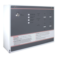
The FP4E 4 Zone Economy Fire Alarm Control Panel (Part No. FF384-3) is a Class 1 fire alarm control panel designed for fixed wiring installations. It requires installation and maintenance by suitably skilled and technically competent personnel, and must be earthed. No panel connections should be changed while mains or battery power is applied.

Function Description:

The FP4E panel is a conventional fire alarm control panel capable of monitoring up to four detector zones and controlling two sounder circuits. It provides visual and audible indications for various conditions including fire, faults (open circuit, short circuit), power supply issues, and zone isolation. The panel supports both manual call points and automatic smoke/heat detectors. It includes features for testing the power supply, sounder circuits, and detector circuits, as well as ancillary facilities for engineers' testing and zone isolation. The panel can drive up to three repeater panels and offers auxiliary expansion for additional relays and a "Class Change" input.

Important Technical Specifications:

  • Power Supply:
    • Mains Supply Voltage: 220-230 V a.c., 50 Hz / 60 Hz, 185 mA.
    • Internal Power Supply: 27 V d.c. nominal.
    • Total Output Current Limited To: 800 mA.
    • Auxiliary Power Output: 27 V d.c. nominal.
    • Mains, battery charger, and batteries are monitored for failure/disconnection.
  • Detector Circuit:
    • Number of Circuits: 4.
    • Line Fault Monitoring: Open circuit, short circuit (can be disabled), and detector removal (if Electronic Monitoring Unit is fitted).
    • End of Line Resistor (supplied): 6800 Ω, 5% tolerance, 0.25 W (blue, grey, red, gold).
    • Detector Continuity Diodes: Silicon 1N4001 or Schottky type (required if EMU fitted).
    • Call Point Resistor (not supplied): 470 to 680 Ω, 0.25 or 0.5 W.
    • Maximum Detectors per Zone: 20 (maximum detector current = 2 mA).
    • Maximum Manual Call Points per Zone: No limit.
  • Sounder Circuit:
    • Number of Circuits: 2.
    • End of Line Resistor (supplied): 6800 Ω, 5% tolerance, 0.25 W (blue, grey, red, gold).
    • Line Fault Monitoring: Open circuit and short circuit.
    • Outputs Fused At: 1 A.
    • Maximum Total Output Current (all outputs): 800 mA.
    • Maximum No. of Bells @ 25 mA each: 32 (example only).
    • Maximum No. of Electronic Sounders @ 20 mA each: 40 (example only).
    • Auxiliary Relay Contacts: 1A 30 V d.c. max. Voltage-Free.
  • Fuses (all compliant to IEC (EN 60127 PT2)):
    • Mains Terminal Block: 200 mA T 20 mm.
    • Sounder Outputs (F2, F3): 1 A F 20 mm.
    • Battery Fuse (F1): 1.6 A F 20 mm.
    • Auxiliary Output (F4): 1 A F 20 mm.
  • Connection Block:
    • Largest Acceptable Conductor Size: 2.5 mm².
    • Smallest Acceptable Conductor Size: 0.75 mm².
  • Physical:
    • Enclosure (Width x Height x Depth): 322 x 267 x 92 mm.
    • Weight (without batteries): 4.3 Kg.
    • IP Rating (to EN 60529): IP30 (when correctly installed).
  • Environmental:
    • Operating Temperature: -10°C to +40°C.
    • Humidity: 5% to 95% RH (non-condensing).
  • Quiescent Current / Battery Stand-by Time:
    • Quiescent Current (mA): 50.
    • Max. Load Current (A): 0.8.
    • Stand-by Time (HRS) 2.0 Ah Batteries: 32.
    • Stand-by Time (HRS) 2.6 Ah Batteries: 44.
    • Stand-by Time (HRS) 4.0 Ah Batteries: 72.

Usage Features:

  • Controls: External pushbuttons (keyswitch activated) for Reset/Resound/Test Zone Lamps, Silence Alarm Sounders, Silence Fault Sounders, and Evacuate. Internal controls for Engineer Detector Test and Zone Isolate.
  • Indicators: External indicators for Sounder Fault, Power Supply Fault, Mains On, Zone Fire, and Zone Fault. Internal indicators for Open Circuit Zone Fault, Short Circuit Zone Fault, Zone Isolated, and Engineer Test Selected.
  • Keyswitch Operation: The panel operates in "Normal" and "Arm Controls" positions. In "Arm Controls," pushbuttons become active for system control and testing.
  • Ancillary Facilities:
    • Engineers Test (Non-Latch Test) Facility: A non-latching test mode for automatic reset of manual call points and smoke detectors. Activated by moving link 'PL1'.
    • Zone Isolation Facility: Individual detector zones can be isolated by moving links (PL2/PL4/PL5/PL6).
    • Revert to Short Circuit = Fire: This facility overrides short circuit fault monitoring for each zone, allowing the panel to be used with installations without Call Point Resistors. Activated by cutting wire links (LK1/LK2/LK3/LK4).
    • Auxiliary Expansion Plug (PL10): Provides connections for Repeater Panels, Fire and Fault relays, and a "Class Change" input.
    • AUX 24V +VE Output: A regulated, unmonitored, 1A (F4) fused output. Can be continuous or switched off when sounders are activated, or if panel power fails.
    • Voltage Free Relay Contacts: Single pole relay outputs (normally closed, common, normally open) rated 30Vdc and 1.0A, which change over when sounders are activated.

Maintenance Features:

  • Installation Procedure: Detailed instructions for cable installation (BS 7671, BS 5839-1), mains wiring segregation, and use of fire-resistant screened cable.
  • Testing Procedures: Comprehensive tests for power supply, sounder circuits, and detector circuits (normal, open circuit fault, short circuit fault, fire condition) are outlined.
  • Battery Management: Instructions for positioning and connecting 12V sealed lead acid batteries. Caution against incorrect battery replacement type and reverse connection.
  • Fault Finding: The manual guides users to investigate and rectify faults indicated on the panel during power-up and testing.
  • Fuse Information: Important note regarding fuse ratings to prevent equipment damage and ensure safety.
  • EOLR (End of Line Resistor) Management: Instructions for fitting and removing EOLRs in sounder and detector circuits.

C-TEC FP4E Specifications

General IconGeneral
BrandC-TEC
ModelFP4E
CategorySmoke Alarm
LanguageEnglish