1) WIRE DIAGRAM .........................................................................................19
2) ENCODER WIRING .....................................................................................20
3) AUTOSET ..................................................................................................20
4) PROGRAMMING ........................................................................................20
5) PARAMETERS, LOGIC AND SPECIAL FUNCTIONS .......................................21
5.1 PARAMETERS (PAR) ......................................................................... 21
5.2) LOGIC (LOG) .................................................................................... 22
5.3) RADIO (RAD) ................................................................................... 24
5.4) CYCLES NUMBER (NMAN) ................................................................ 24
5.5) MAINTENANCE CYCLES (MACI) ....................................................... 24
5.6) RESET (RES) ................................................................................... 24
5.7) AUTOSET (AUTO)............................................................................. 24
5.8) PROTECTION CODE (CODE) ............................................................. 25
6) TRANSMITTERS REMOTE LEARNING .........................................................25
7) FUSES .................................................................................................... 25
8) BACK UP BATTERIES .................................................................................26
9) DIAGNOSTICS ...........................................................................................26
10) ERROR MESSAGES .................................................................................26
INDEX
17
EN
HYBRA 24 CONTROL UNIT
ARC CONTROL UNIT
IMPORTANT, PLEASE READ CAREFULLY:
The radio receiver in this product is compatible ONLY with the new ARC (Advanced Rolling Code) transmitters which, thanks to 128-bit encryption
ensure superior copy-security.
Storing new ARC transmitters is quite similar to that of normal rolling code transmitters with HCS coding
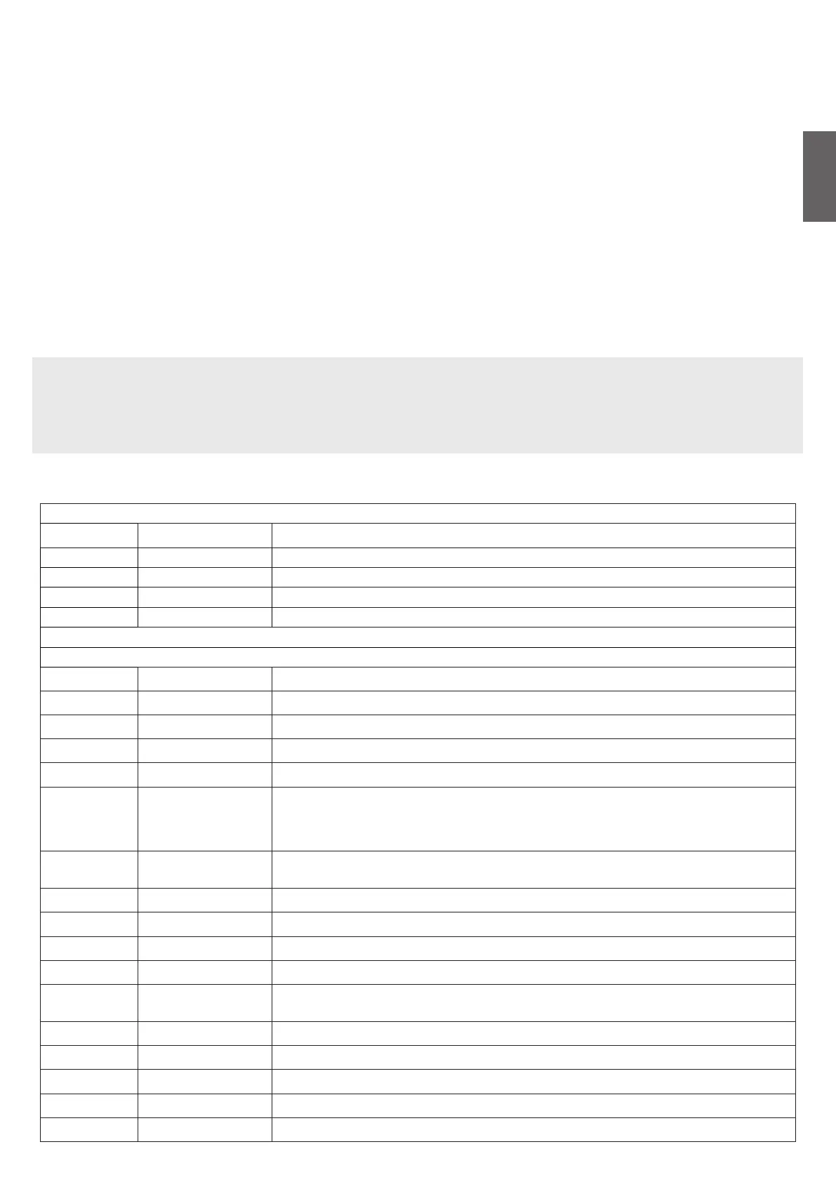
1) WIRE DIAGRAM
Wire connections shown in Fig. 1 are described hereunder:
SAR.24V
Terminal Function Description
L-N-GND Power supply Power supply input (115V ± 10% or 230V ± 10%) selectable via terminal M4
M4 Power supply selection WARNING: to use the central unit with 115V power supply, it is necessary to jumper this terminal.
+ 24V - Output 24Vdc Controller HYBRA 24 power supply output 24 Vdc
+BAT- Batteries Clamp input for connection of back-up batteries (accessory).
HYBRA 24
Terminal No. Function Description
1-2 Motor 1 Connection, motor 1: 24VDC 16A max
3-4 Motor 2 Connection, motor 2: 24VDC 16A max
5-6 Flashing light Connection, flashing light 24VDC 15W max.
7-8 Lock Output, 12Vdc/10W power supply for electric lock (7:0V, 8:+12V)
9-10 AUX1
N.O. contact free from voltage can be configured via the AUX1 parameter as:
Open gate indicator (SCA), second radio channel (2nd CH), courtesy light (TLS), zone light, photocell
test contact (PHOTEST).
See parameter AUX1
11-12 24 Vdc
Output, accessory power supply, 24VAC/0.5A max.
Make sure the devices are correctly connected (i.e. 11:+24Vdc / 12:-0Vdc).
13-17 Limit switch inputs Do not use the limit switches in this version. DO NOT REMOVE the jumpers.
18 PHOT Input, photocell activated in both opening and closing phases
19 PHOT C Input, photocell activated in closing phase only (Normally closed contact)
20 STOP Input, STOP push-button (Normally closed contact)
21 OPEN
Input, OPEN push-button (Normally open contact).
It is possible to connect a timer for opening in time slots.
22 CLOSE Input, CLOSE push-button (Normally open contact)
23 PED Pedestrian button input (N.O. Contact), controls the motor 1 opening, see TPED parameter.
24 Step-by-Step Input, step-by-step push button (Normally open contact)
25 COM Common for Limit switch and all the command inputs.
26 - Input - Encoder Motor 1
 Loading...