001-5006-000_FCC.docx Page 11
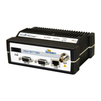
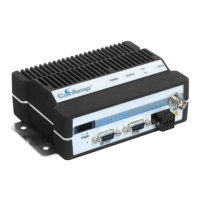
The front panel has the following connections:
(1) 8-Pin user interface block connector
(1) 50-ohm TNC female Antenna connector
(1) 50-ohm SMA female receive antenna connector (Dual-Port models only)
(1) Right-angle power connector (10-30 VDC)
(2) DE-9F RS-232 ports
For Dual-port Guardian connections, see Section 1.3.6.
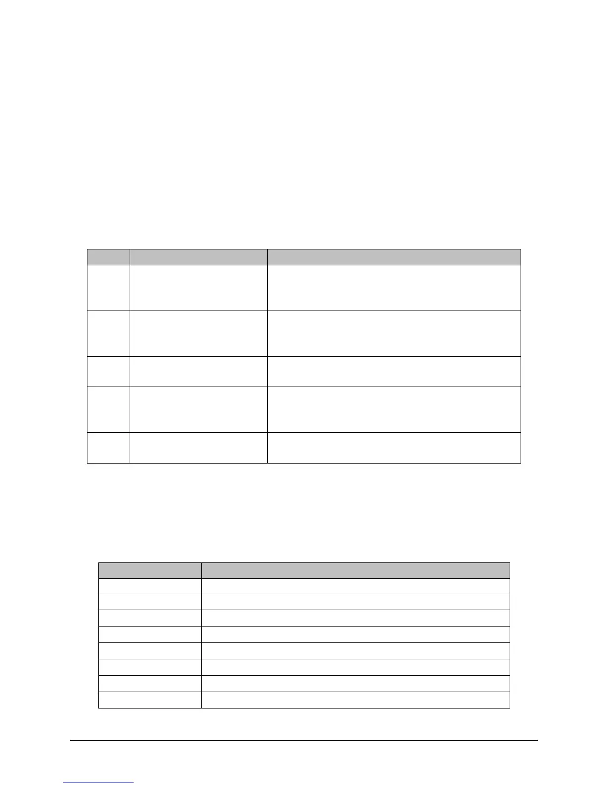
1.3.2 LED Panel
The LED panel has five Tri-Color LEDs. The functionality of each LED is shown in Table 1.1.
Table 1.1 Guardian LED Functionality
Green
Amber (Solid or Blinking)
Red
Guardian ready, normal operations
Guardian is Programing
Guardian hardware fault
Green
Red
Amber (Solid or Blinking)
Guardian no faults, normal operations
Guardian has a fault condition, check unit status
Guardian detects high background noise
Transmitting data
The unit wants to transmit, but is inhibited.
Receive data is being sent out of the port
Transmit data is being received by the port
1.3.3 User Interface Port
The user interface port is an 8 pin block receptacle, programmable to work with 1.8V to 5V
levels. Table 1.2 shows pin-out descriptions for the RJ-45 port.
Table 1.2 Pin-out for User Interface Port Contacts
 Loading...