6
48
103
20
10
150
28
35
62
117
90
68
5
10
2
1.5
20
3
15
7
1 in
1 1/4 in
3/4 in
1/2 in
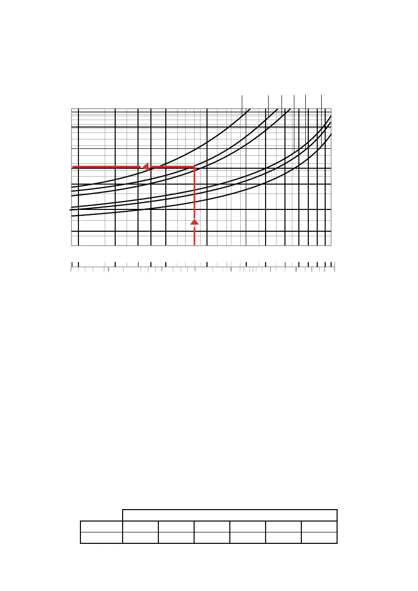
FALL OFF PRESSURE
Reference values: Upstream pressure = 116 psi (800 kPa)
Downstream presssure = 43 psi (300 kPa)
14
∆
p (psi)
∆
p (kPa)
1 1/2 in
2 in
20
90
Flow rate
(/s)
(gpm)
30
40
10
5
2
1
0.9
5
50
60
70
1
2
0.5
0.2
0.1
0.05
3
4
6
1.5
0.3
0.4
2.5
80
3
4
Graph 2 (Pressure drop)
Sizing procedure
Flow velocity is recommended to be kept within 3 to 6 feet per second when calculating the
correct pressure reducing valve size. This will prevent noise in the pipes and rapid wear of
appliances.
The correct diameter of the pressure reducing valve is taken from graph 1 on the basis of the
design flow rate taking into account an ideal flow velocity of between 3 and 6 f/s (blue band).
Example:
For 8 gpm, select the ¾” size valve (see arrow on graph 1).
The pressure drop is taken from graph 2 also on the basis of where the design flow rate
intersects the curve for the valve size already selected (the downstream pressure falls by an
amount equal to the pressure drop, with respect to the set pressure at no flow condition).
Example:
For 8 gpm the Dp = 7.3 psi (see arrow on graph 2).
Design Flow Rate
Size ½" ¾" 1" 1¼" 1½" 2"
gpm 4 to 7.3 7 to 12.5 10 to 19 17 to 34 24 to 44 37 to 70