7
Montaggio
Mounting
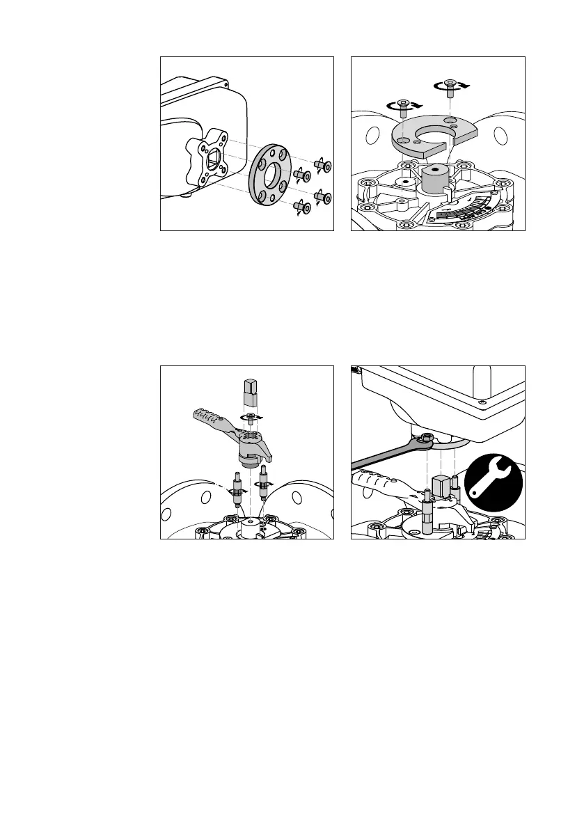
Applicare le flangia alla base del motore
mediante l’utilizzo delle quattro viti
apposite e con le svasature rivolte verso
il basso.
Apply the flange to the base of the motor
using the four screws provided and with
the flared rims facing downwards.
(solo per DN 100 - DN 125)
Applicare la flangia adattatrice sul corpo
valvola mediante l’utilizzo delle due viti
apposite.
(for DN 100 - DN 125 only)
Apply the adapter flange to the valve
body using the two screws provided.
1
3
2
3
10
4
5
6
1. Installare la manopola di comando
sul corpo valvola fissandola tramite
l’apposita vite centrale.
2. Inserire l’adattatore F05 nell’apposito
alloggiamento presente sulla
manopola di comando.
3. Avvitare i perni negli appositi fori
filettati.
1. Fit the control knob on the valve body
by securing it with the corresponding
central screw.
2. Fit the F05 adapter into the
corresponding housing on the control
knob.
3. Screw the pins into the corresponding
threaded holes.
4. Assicurarsi di allineare la manopola di
comando posta sul corpo valvola con
quella presente sul motore, in modo
che l’adattatore F05 sia allineato con
l’alloggiamento del motore.
5. Allineare i perni laterali ai fori presenti
sulla flangia del motore.
6. Fissare il motore mediante i due dadi.
4. Make sure the control knob on the
valve body is aligned with the control
knob on the motor, so that the F05
adapter is aligned with the motor
housing.
5. Align the side pins with the holes on
the motor flange.
6. Secure the motor using the two nuts.
Code 638022
 Loading...