4
2. INSTALLATION AND MAPPING (to be carried out by the installer)
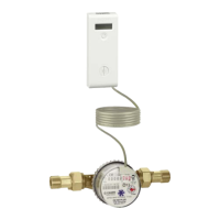
Characteristic components
1 Tamper-proof seal
2 Acquisition device complete with PCB
3 Protection for tamper-proof element (to be removed during
installation)
4 Display selection key
5 Wall mounting screws (tightening torque 0.8-1 N·m)
6 Plastic plate for wall mounting
7 Wall mounting wall anchors
MONITOR 2.0 PULSE - code 720030
3
4
5
6
7
2
1
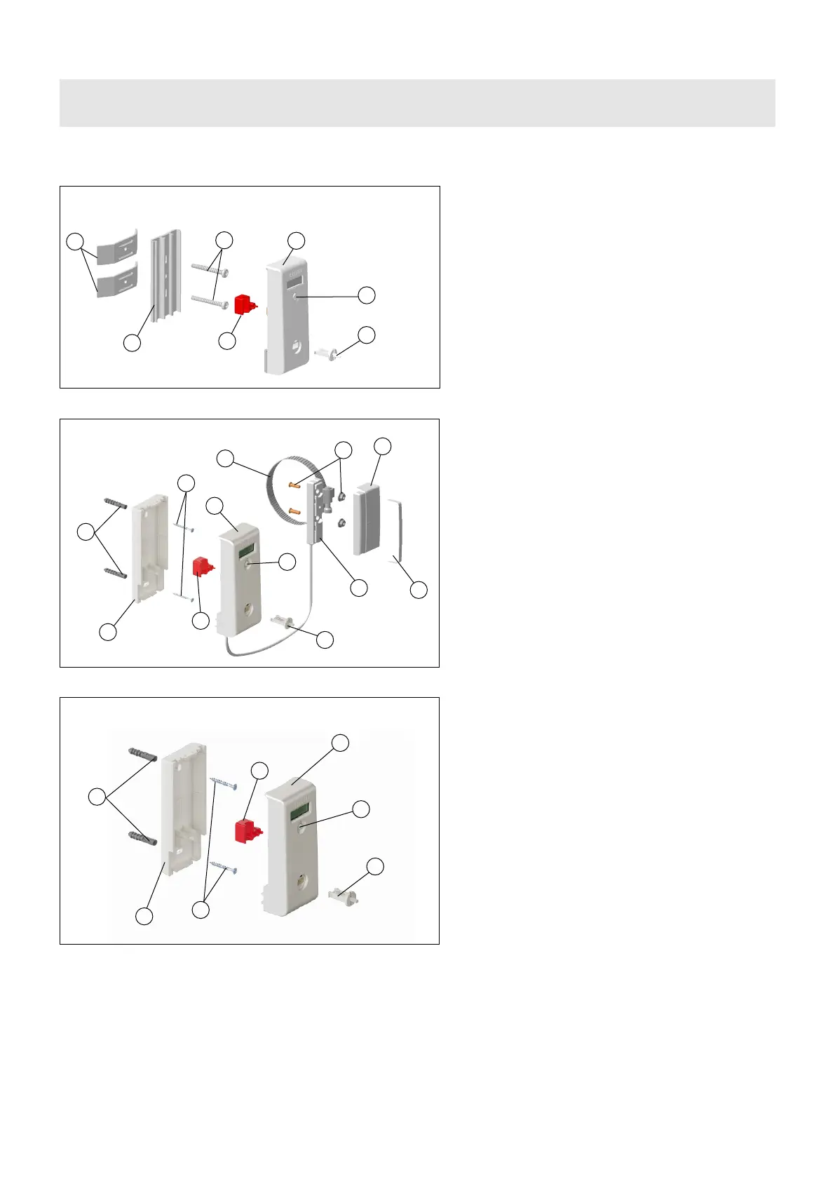
1 Tamper-proof seal
2 Heat cost allocator complete with PCB
3 Radiator probe protection (to be removed during
installation)
4 Display selection button
5 Retaining screws (tightening torque 0.8-1 N·m)
6 Aluminium thermal coupling plate
7 Fastening brackets
1 Anti-tampering seal
2 Heat cost allocator complete with PCB
3 Protection for the tamper-proof sensor (to be removed
during installation)
4 Display selection button
5 Wall fastening screws (tightening torque 0.8-1 N·m)
6 Aluminium plate + spacers
7 Wall fastening anchors
8 Metal clamp for fastening the extended probe to the
radiator/convector
9 Copper stud bolts + nuts for welded fastening
10 Remote probe
11 Remote probe cover
12 Tamper-proof label
3
4
5
6
7
2
1
MONITOR 2.0 - code 720020
3
4
5
6
7
8
9
10
11
12
2
1
MONITOR 2.0 E (remote probe) - code 720025
 Loading...