This document describes the XT-2150 GPS Tracker, a device designed for vehicle tracking and monitoring. The manual covers installation, operational checks, and troubleshooting, providing a comprehensive guide for users.
Function Description
The XT-2150 is a GPS tracking device primarily used for monitoring vehicles. Its core function is to transmit location data and other operational information to a host server, which can then be accessed by the user through a web platform. The device utilizes both GPS and GSM cellular networks to achieve its tracking capabilities.
Key functionalities include:
- Location Tracking: Continuously monitors the vehicle's position using GPS.
- Status Monitoring: Provides real-time updates on the device's operational status, including GPS lock and cellular network connectivity.
- Ignition Sense: Detects when the vehicle's ignition is on or off, providing valuable data for usage patterns.
- Data Transmission: Transmits collected data to a host server via the cellular network.
- Geofencing: Allows users to define geographical boundaries and receive alerts when the vehicle enters or exits these areas.
Important Technical Specifications
While the document doesn't list explicit technical specifications like dimensions or power consumption in detail, it does provide crucial information regarding its power requirements and communication protocols.
Power Supply:
- The device operates on a 12V power supply.
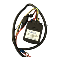
- It requires a constant 12V connection (Red cable) and a ground connection (Black cable).
- An additional "Ignition Sense" wire (White cable) is used to detect the vehicle's ignition status.
Communication:
- GPS: Utilizes GPS for accurate location determination.
- GSM Cellular Network: Relies on a GSM cellular network for data transmission to the host server. This requires a SIM card to be installed in the device.
LED Indicators:
The device features a blue status LED that provides visual feedback on its operational status.
- Blinking once every 3 seconds: Indicates the device is powered on, searching for a GPS lock, and attempting to connect to the cellular network.
- Blinking once every second: Indicates the device is powered on, has a GPS lock, and is connected to the cellular network.
- Solid: Indicates the device has a GPS lock and is connected to the cellular network.
Usage Features
The XT-2150 is designed for straightforward installation and operation, with features aimed at ease of use and effective vehicle monitoring.
Installation:
- Wiring: The installation involves connecting three wires: Red (12V power supply), Black (Ground), and White (Ignition Sense).
- GPS Tracker Position: For optimal performance, the device should be installed with the label facing right direction (e.g., if the label on the unit says, "Label side down", then the unit should be installed so that the Label side faces down). It's also recommended to ensure the GPS unit has access to GPS signals, meaning the install position should provide this access.
- SIM Card: A SIM card must be inserted into the device for cellular communication.
Operational Checks:
- LED Status: The blue LED is the primary indicator of the device's operational status. Users can quickly assess if the device is powered, has a GPS lock, and is connected to the cellular network by observing the LED's blinking pattern.
- Web Platform: After installation, users can log into a web platform to verify that the device is transmitting data correctly. The platform should display the device's location and status updates.
Geofencing:
- This feature allows users to define specific geographical areas. The system can then generate alerts when the tracked vehicle enters or exits these predefined zones, which is useful for managing vehicle movement and security.
Login and Account Management:
- Users receive login details via mail to access their account on the web platform.
- The web platform provides access to all logged information, including vehicle location, status, and historical data.
Maintenance Features
The manual provides guidance on troubleshooting common issues, particularly concerning data transmission and device updates, which can be considered maintenance-related.
Troubleshooting "Connect the GPS Tracker":
- If the blue status LED is blinking at the rate of once every 3 seconds, it indicates the device is powered on but still searching for a GPS lock and/or cellular network connection.
- The manual specifies that the device should have a GPS lock and be connected to the cellular network, with the blue LED blinking at the rate of once every second, within 1-2 minutes of being powered on. If this doesn't happen, users should check the available connection with the cellular network.
- Final installation should only be done after the blue LED blinks at the rate of once every 3 seconds, implying that the device has acquired a GPS lock and is connected to the cellular network.
Troubleshooting "Additional Check (Optional)":
- If the device is not updating on the web portal, users should ensure the white cable (ignition sense) is connected to the power supply for a few minutes. This allows the device to update its firmware and transmit data.
- If the device location is still not updating, it's crucial to ensure the white cable remains permanently connected to the power supply as it will drain the vehicle battery when not running. This suggests a continuous power supply is needed for optimal operation and updates.
Troubleshooting "After installation if the unit is not updating":
- LED Status Check: The first step is to check the blue LED. It should be blinking at a rate of once every 3 seconds. If not, there might be a power issue.
- Ignition Cycle: If the blue LED is blinking at the rate of once every 3 seconds, users should start the vehicle engine and keep it running for a few minutes to get a quick update.
- Web Platform Update: If the engine is off, the web platform updates at once in 2 hours. If the engine is on, the update rate is once every 1 or 2 minutes.
- Ignition Sense Wire Check: If the engine is on and the web platform is updating at once every 2 hours, it indicates that the ignition sense wire (white cable) was not connected. This needs to be connected for real-time updates (at 1 minute intervals).
- Contact Support: If all the above steps are followed and the unit still does not update, users are advised to contact support.
These maintenance guidelines emphasize the importance of correct wiring, monitoring LED indicators, and understanding the device's update behavior based on ignition status to ensure continuous and accurate tracking.