Do you have a question about the Calpeda I-MAT 65,4 TT-D and is the answer not in the manual?
Explanation of symbols used in the manual for understanding warnings and information.
Details of the manufacturer, Calpeda S.p.A., including their address and website.
Defines authorized operators and user responsibilities for safe operation and maintenance.
Information regarding product warranty coverage and conditions for invalidation.
Contact information for obtaining further documentation, technical support, and spare parts.
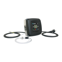
Specifies the intended application of the frequency converter for pumps in various systems.
Outlines forbidden uses of the device and manufacturer's disclaimer for improper application.
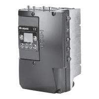
Details about the product nameplate information and its components.
Presents efficiency data for the IMAT inverter at various operating points, meeting IE2 classification.
Lists key technical specifications such as supply voltage, IP protection, and display type.
Specifies the environmental and operational conditions required for proper product functioning.
Introduces the I-MAT frequency converter and its supported operating modes for pumps.
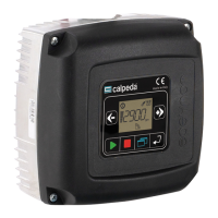
Describes the functions of the 6 pushbuttons on the device's user interface.
Details the graphic interface of the display, divided into system icons, display area, and operating icons.
Explanation of various system icons displayed on the frequency converter.
Description of the display area, including its proportional bar and measurement unit.
Illustrates and explains the icons representing different operating modes of the system.
Guidance for operating submersible pumps or with long cables, referencing specific paragraphs.
States that the frequency converter is not suitable for use with a Generator set.
Covers EMC compliance, classification, and requirements for network harmonics.
Essential safety information and standards to be acknowledged before product use.
States that the device has no residual risks based on its design and intended safety standard.
Highlights safety icons and related information for proper use and hazard awareness.
Recommends using appropriate tools during installation, pump start, and maintenance.
Instructions for safe handling of the product package, including precautions against impacts.
Instructions to ensure the device has not been tampered with during unpacking.
Guidance for connecting the heat-sink with the motor adapter for motor-mounted installations.
Instructions for installing the frequency converter on a wall or in an electric control box.
Details on performing electrical connections by qualified personnel, following safety standards.
Information on connecting the electrical supply, including differential switch requirements.
Guidance on configuring the converter for IT power grid supply, also known as isolated ground supply.
Instructions for connecting the motor cable, emphasizing EMC standards and shielded cables.
Details on connecting analog instruments (transducers) for monitoring system parameters.
Instructions for connecting up to two float switches for dry-run protection.
Details on connecting a switch to enable operation with maximum or minimum curves.
Instructions for connecting a switch to enable operation with an alternative set-point.
Details on connecting a switch for remote control of the pump's start and stop functions.
Instructions for connecting up to two alarm signals for remote monitoring.
Guidance on using the analog output for remote monitoring of frequency converter parameters.
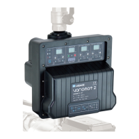
Guidelines for installing frequency converters in pressure boosting sets with multiple pumps.
Instructions for electrical connections in cascade mode, including circuit breaker requirements.
Procedure for installing the cascade mode expansion board correctly.
Wiring details for connecting multiple variable speed pumps in cascade mode.
Wiring instructions for cascade mode involving one variable speed and multiple fixed speed pumps.
Overview of displayed information including pump status, programming parameters, and alarms.
Describes how to visualize pump status, transducer measurements, and current absorption.
Details on accessing and navigating programming parameters, including different setting categories.
Step-by-step guide for entering programming mode and modifying parameter values.
Procedure for entering passwords to access protected menus and parameters.
Instructions for resetting the frequency converter to its factory default settings.
Key parameters to verify during initial unit startup for correct operation.
Details on setting up and configuring the constant pressure operating mode.
Instructions for configuring the proportional pressure operating mode for variable demand.
Guidance on setting up constant temperature operation for heating or cooling systems.
Information on configuring the system to maintain a constant flow rate.
Configuration options for operating the pump at a fixed speed, controlled by keyboard or externally.
Details on enabling and configuring the optional night mode to reduce system frequency.
Description of the dry-run protection feature and its configuration with float switches.
How to enable operation using maximum or minimum pump curves via an input signal.
Instructions for enabling an alternative set-point using an input signal.
How to enable remote control for starting and stopping the pump.
Details on connecting and configuring remote alarm signals.
Setting up the analog output to monitor parameters on a remote unit.
How to modify the set-point value remotely using a secondary transducer signal.
Configuration for a function that allows the pump to run periodically when in standby.
Functionality to check the number of starts and detect system leakage.
How to enable motor heating when the pump is stopped or in standby.
Feature to prevent pressure peaks by controlling the start frequency after power restoration.
Configuration for twin-pump operation modes, allowing one pump for reserve.
Enables uniform use of pumps by alternating their operation, with adjustable time settings.
Procedure for starting a plant in cascade mode, checking parameters.
Instructions on how to change the motor's direction of rotation through parameter settings.
Guidance on setting the vessel pre-charge pressure relative to pump startup pressure.
List and description of user-configurable parameters (UP series).
List and description of advanced parameters (AP series) for technical use.
List and description of service assistance parameters (SA series).
Detailed list of parameters for the Pressure Constant operating mode.
Detailed list of parameters for the Proportional Pressure operating mode.
Detailed list of parameters for the Constant Temperature operating mode.
Detailed list of parameters for the Constant Flow Rate operating mode.
Detailed list of parameters for the Fixed Speed Pump operating mode.
Selection of filters for reducing radiated and electromagnetic noise emissions.
Details on capacitor kits available for different I-MAT models and their mounting.
Information on optional expansion cards for cascade mode and Modbus communication.
List of available connectors, such as M12 types, for HMI and Modbus connections.
Diagram illustrating the motor-mounted installation of the frequency converter.
Diagram showing the wall-mounted installation of the frequency converter.
Electrical connection diagram for the I-MAT 5,2TT-A model.
Electrical connection diagram for the I-MAT 11,2TT-B model.
Electrical connection diagram for the I-MAT 25,8TT-C model.
Electrical connection diagram for the I-MAT 65,4TT-D model.
Electrical connection diagram for the I-MAT 119TT-E model.
Diagram illustrating digital and analog signal connections.
Diagram showing analog input connections (AIN1).
Diagram illustrating analog input connections (AIN1).
Diagram showing analog input connections (AIN2).
Diagram illustrating analog input connections (AIN2).
Diagram for remote parameter monitoring output connection.
| Brand | Calpeda |
|---|---|
| Model | I-MAT 65, 4 TT-D |
| Category | Media Converter |
| Language | English |