EasyManua.ls Logo

Calpeda QMLD 1D 12A-FA User Manual

Calpeda QMLD 1D 12A-FA
28 pages
Go to English
To Next Page IconTo Next Page
Page #1 background imageLoading...
Page #1 background image
Quadro elettrico di comando 1 pompa da drenaggio con motore monofase.
Electrical control panel for 1 drainage pump with single-phase motor.
Coffret électrique de commande 1 pompe de drainage avec moteur monophasé.
Электрический пульт управления для 1 дренажных насосов с монофазным двигателем.
QMLD 1D 12A-FA
ISTRUZIONI ORIGINALI PER L’USO P 385.01 I Pagina 2 Italiano
ORIGINAL OPERATING INSTRUCTIONS P 385.01 GB Page 8 English
INSTRUCTIONS ORIGINALES POUR L’UTILISATION
P 385.01 F Page 14 Français
ОРИГИНАЛЬНЫЕ ИНСТРУКЦИИ ПО ЭКСПЛУАТАЦИИ
P 385.01 RU ëÚ‡Ìˈ‡ 20 êÛÒÒÍËÈ
Question and Answer IconNeed help?

Do you have a question about the Calpeda QMLD 1D 12A-FA and is the answer not in the manual?

Calpeda QMLD 1D 12A-FA Specifications

General IconGeneral
TypeControl Panel
ModelQMLD 1D 12A-FA
BrandCalpeda
Current12A
Protection DegreeIP55
Voltage230V

Summary

1. Types

2. Operating conditions

3. Components

Standard construction

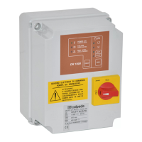
Outlines the basic build of the control panel.

Components List

Lists individual parts such as fuses, relays, and the electronic card.

3.1. DR 1000 electronic card

Automatic functioning test

Details the periodic pump self-test every 48 hours.

Pump control with signals

Explains pump operation based on float switch inputs.

3.1.1. Settings of the DR 1000 electronic card

FAILURE LED Settings

Interprets the FAILURE LED to determine float switch configuration.

MAXIMUM LEVEL LED Settings

Interprets the MAX LEVEL LED for thermal protector configuration.

4. Installation

5. Electrical connection

Proper Earthing

Emphasizes the necessity of proper grounding for safety compliance.

Cable Gland Fastening

Describes securing input/output cables using cable gland ferrules for a clean installation.

5.1. Capacitor connection

5.2. Motor connection

5.3. Float switches connections

2 Float Switches Connections

Wiring instructions for connecting two float switches for pump control and alarm.

3 Float Switches Connections

Wiring instructions for connecting three float switches for pump control and alarm.

5.4. Control panel for remote alarm

6. Amperometric protection setting

Calibration Procedure

Details the steps to set the amperometric protection using the potentiometer and LED indicator.

7. Operating

7.1. Operating with 2 float switches

Activating 2 Float Switches Function

Describes how to configure the panel for two float switches if it's set for three.

7.2. Operating with 3 float switches

Activating 3 Float Switches Function

Describes how to configure the panel for three float switches.

8. Motors with thermal protector

Motor Types

Outlines motor configurations with or without thermal protectors.

Thermal Protector Intervention

Explains how the control panel recognizes and signals thermal protector intervention.

8.1. Motors with thermal protector without external signals

Activation of Thermal Protector Function

Details how to set the panel for motors with thermal protectors without external signals.

8.2. Motors without thermal protector

9. Control panels for remote alarm

RA 100E

Description of the RA 100E remote alarm control panel.

RA 100A

Description of the self-powered RA 100A remote alarm control panel.

10. Outside of box cover

11. Inside of the box

12. Declaration of conformity

Related product manuals