DVD89 SERVICE MANUAL
TABLE OF CONTENTS
Safety Precautions
3
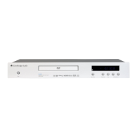
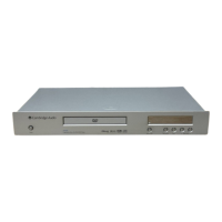
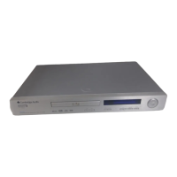
Front Panel Illustration
4
Prevention of Static Electricity Discharge
5
Mechanism Unit Exploded Diagram
6
Bracket Exploded View and Parts List
7
Protection of the Laser Diode
8
Video Output Confirmations – Luminance & Chrominance Signal
9
HY57V641620HG Pin Configuration & Description (U211)
10
HY57V641620HG Functional Block Diagram (U211)
11
MT1392 Pin Definitions (U203)
12/13/14
MT1392 System Configuration & Functional Block (U201)
15
MT1392 Functions (U201)
16
MT1392 Pinout Diagram (U201)
17
MT1389 Pinout Diagram (U201)
18
MT1389 Block Diagram (U201)
19
MT1389 Pin Function (RF Interface) (U201)
20
MT1389 Pin Function (Analog Monitor Output) (U201)
21
MT1389 Pin Function (General Power / Ground, Micro Controller & Flash Interface) (U201)
22
MT1389 Pin Function (Micro Controller & Flash Interface) (U201)
23
MT1389 Pin Function (Audio Interface) (U201)
24
MT1389 Pin Function (Video Interface) (U201)
25
MT1389 Pin Function (DRAM Interface) (U201)
26/27
MT1389 Pin Function (DRAM Interface & JTAG Interface) (U201)
28
Front Panel & VFD Schematic
29
Front Panel & VFD Board Layout
30
Power Supply Schematic
31
Power Supply PCB Layout
32
Main PCB Board (Main Processor)
33
Main PCB Board (Memory, Reset & Main Clock)
34
Main PCB Board (Audio DACS, Output Filters & Mute)
35
Main PCB Board (DVI & HDMI)
36
Main PCB Board (Video Outputs)
37
Main PCB Board Layout
38
Power Board Parts List
39
Main Panel Parts List
40
Decode Board Parts List
41/42
Serviceable Parts List
43
 Loading...