EasyManua.ls Logo

Camco 92A61633010000 User Manual

Default Icon
24 pages
To Next Page IconTo Next Page
Page #1 background imageLoading...
Page #1 background image
INSTALLATION AND OPERATING INSTRUCTIONS
VARI-PAK
CYCLING DC MOTOR CONTROL
Designed for Indexing Applications
© 2003 KB Electronics, Inc.
OLSTOPON
JOG / STOP
RUN
DC MOTOR SPEED CONTROL
VARI-PAK
NEMA-12
100
90
80
70
60
40
30
20
10
0
50
%
144 S. Wolf Rd
Wheeling, IL 60090
(847) 459-5200
See Safety Warning on Page 2
The information contained in this manual is intended to be accurate. However, the manufacturer
retains the right to make changes in design which may not be included herein.
This manual covers the following CAMCO part numbers:
92A61633010000, 92A61633020000, 92A61633030000, 92A61633040000
Industrial Motion Control, LLC
Question and Answer IconNeed help?

Do you have a question about the Camco 92A61633010000 and is the answer not in the manual?

Camco 92A61633010000 Specifications

General IconGeneral
BrandCamco
Model92A61633010000
CategoryControl Unit
LanguageEnglish

Summary

Simplified Operating Instructions

Power and Motor Connections

Connects AC power to L1/L2 and motor armature to A1/A2, ensuring voltage match.

Current and Speed Setup

Sets motor current via J1 and adjusts MIN/MAX trimpots and main speed potentiometer.

Cycle on Demand Application Note

Special instruction for cycle on demand applications, starting on this page.

Safety Warning!

Safety Precautions and Warnings

Covers general safety, circuit warnings, CE compliance, and required accessories.

Introduction to VARI-PAK Series

VARI-PAK Series Overview and Features

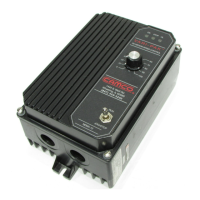
Introduces the unit, its enclosure, indexing application design, and key functions.

Mounting the Control Unit

Mounting Location and Cover Handling

Mount vertically with clearance; instructions for front cover opening and closing.

Setting Motor Current with Jumper J1

Jumper J1 Functionality and Horsepower

Jumper J1 sets armature current range, linked to horsepower via Table 4.

Wiring the Control Unit

Wiring Safety and Practices

Adherence to NEC, fusing, avoiding wire bundling, and terminal block specs.

Logic Wire Management, Grounding, and Connections

Guidelines for logic wires, grounding, AC line, motor, and potentiometer connections.

Remote Potentiometer and Analog Input

External Speed Control Options

Connect external potentiometers or 0-10VDC analog voltage for speed control.

Fusing Requirements

AC Line Fusing Requirements

Electrical codes require fusing on ungrounded conductors; control has no internal fuses.

Logic Functions and Wiring Guidelines

Logic Wiring Precautions

Avoid using logic functions as safety stops; do not bundle logic with power wires.

RUN Terminal Operation

Describes the "RUN" terminal for continuous operation via momentary or maintained contact.

JOG Command Operation

STOP Terminal Function

RETURN (RTN) Terminal Function

Power Supply and Common Terminal

+24 VDC Supply and COM Terminal

Details the +24 VDC output and the "COM" terminal as logic reference.

Application Wiring Diagrams (General)

Solid-State Logic Inputs

Using solid-state devices for logic commands, requiring specific ratings.

Logic Input Contact Ratings

Cycle on Demand Functionality

Limit Switch Triggering

How limit switches on the camshaft signal the start and stop of the cycle.

Cycle on Demand Setup

Jumper JW and JR Configuration

Set Jumpers "JW" to "R" and "JR" to "F" for Cycle on Demand operation.

Limit Switch LS1 Wiring

Wire the normally closed limit switch LS1 for the Cycle on Demand sequence.

Application Wiring Diagrams (Reversible Models)

Reversing Operation Features and Stop Logic

Describes reversing, lockout, and changing stop logic via Jumper JS.

Control Operation

Control Start-up and Motor Direction

Steps for initial start-up, checking indicators, and correcting motor direction.

Trimpot Adjustments

Trimpot Location and Adjustment Use

Illustrates trimpot locations and explains their use for application-specific adjustments.

Minimum Speed (MIN) Adjustment

Maximum Speed (MAX) Adjustment

Current Limit (CL) Adjustment

IR Compensation (IR) Adjustment

Function Indicator Lamps

Power On (ON) and Stop (STOP) Indicators

Green "ON" LED for power, Yellow "STOP" LED for control status.

Overload (OL) Indicator

Red LED indicates current limit setpoint reached or a fault condition exists.

Troubleshooting Guide

Motor Operation Issues

Diagnosing problems like motor not running, fuse blowing, or braking failure.

Speed Control Problems

Troubleshooting steps for issues with speed control and motor RPM.

Related product manuals