Do you have a question about the Camco VARI-PAK and is the answer not in the manual?
Use 120 Volt AC rated controls on 120 Volts AC and 240 Volt AC rated controls on 240 Volts AC.
Connect motor leads to TB2 terminals A1 and A2, ensuring voltage rating matches.
Set Jumper J1 to match the approximate rated motor current (e.g., 10A, 5A, 3.3A, 2A).
Trimpots should be set to their approximate factory positions.
Turn the front cover speed potentiometer to 15% or greater.
Read and follow all safety warnings. Use insulated tools and wear eye protection. Proper installation and grounding are essential.
Logic circuits (Start/Stop/Inhibit) are not fail-safe. Use AC line for safety disconnects.
Potentiometer circuit is not isolated from AC line. Follow instructions carefully to prevent shock or fire.
Product complies with CE directives. CE approved RFI filter and shielded cables may be required.
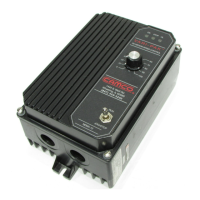
Description of the VARI-PAK Series, its enclosure, and applications for cycling and indexing.
Features include isolated logic functions (STOP, JOG, RUN), jumper J1 for DC current selection, and onboard controls.
Mount vertically on a flat surface in a suitable location, avoiding extreme hazards and explosion proof applications.
If enclosed, allow for heat dissipation. Minimum 12" W x 24" H x 12" D for full rating.
Open by loosening four screws. Close carefully, ensuring gasket is compressed but not overtightened.
J1 sets armature current range, adjustable by CL trimpot. Factory settings provided.
Table 4 provides guidance for setting Jumper J1 based on motor horsepower.
Follow National Electrical Code. Fuse each ungrounded conductor. Do not bundle logic wires with power wires.
Connect AC Line to terminals L1 and L2. Ensure control model and rating match AC line input voltage.
Connect motor armature to terminals A1 (+) and A2 (-). Do not wire switches in series with the armature.
Connect ground wire to the Green Ground Screw. Do not connect to other terminals.
Control supplied with prewired potentiometer. Remote operation requires removing leads P1, P2, P3.
Electrical codes require fusing for ungrounded conductors. Control does not contain AC line fuses.
Do not use logic functions (STOP, RTN) as emergency stops. Use AC line disconnect. Avoid bundling logic wires.
Momentary closure between 'RUN' and 'RTN' latches continuous run. Stop circuit must be activated.
Momentary contact closure between 'JOG' and 'RTN' causes continuous run. Drive runs while contact is closed.
Use normally closed (NC) contact between 'STOP' and 'RTN'. Opening contact activates Dynamic Brake.
Determines priority of Run/Stop commands. 'S' for Stop priority, 'R' for Run priority (Cycle on Demand).
Jumper 'JR' to 'O' disables functions. Contact between 'RTN' and 'COM' enables functions.
Provides nominal 24 VDC @ 12 mA output for external loads like proximity switches.
Referenced to logic signals. Jumper 'JR' connects 'RTN' and 'COM' together.
Use NPN transistors or proximity switches for logic commands meeting specific criteria.
Contacts used on logic inputs should be rated for low-level logic switching (gold contacts).
Drive makes one cycle, dwells, and waits for external signal. Motor accelerates during dwell.
Limit switch actuates to signal a stop as indexer re-enters dwell. Stopping in dwell is crucial.
Details wiring for reversing models, enabling forward and reverse indexing with a lockout feature.
Set jumpers and complete wiring. Ensure ON and STOP indicators light. Set main potentiometer to 15%.
If motor rotates incorrectly, disconnect AC power and reverse armature wires.
After power loss, control will not restart unless Run-Jog/Stop Switch is moved to 'Run'.
Sets the minimum motor speed. Rotate main potentiometer to minimum, then adjust MIN trimpot.
Sets the maximum motor speed. Rotate main potentiometer to maximum, then adjust MAX trimpot.
Sets maximum DC current. Factory set at 150% of J1 current. Adjust with DC ammeter.
Stabilizes motor speed under varying loads. Adjust to match loaded speed to unloaded speed.
This lamp glows GREEN when AC line is connected to the control.
This lamp glows YELLOW when the control is in the STOP mode via switch or logic contact.
Glows RED when motor is loaded to current limit. Blinking may indicate transient overload.
Check operation, fuses, logic, speed pot, current limit, and motor brushes.
Causes include improper wiring, incorrect AC voltage, worn motor brushes, or heavy motor load.
Check logic wiring, motor brushes, or contact Industrial Motion Control.
Check speed pot wiring, setup procedure, or contact Industrial Motion Control.
Check MAX SPD trimpot, current limit, line voltage, and motor nameplate voltage.
| Brand | Camco |
|---|---|
| Model | VARI-PAK |
| Category | Control Unit |
| Language | English |