i. SIMPLIFIED OPERATING INSTRUCTIONS
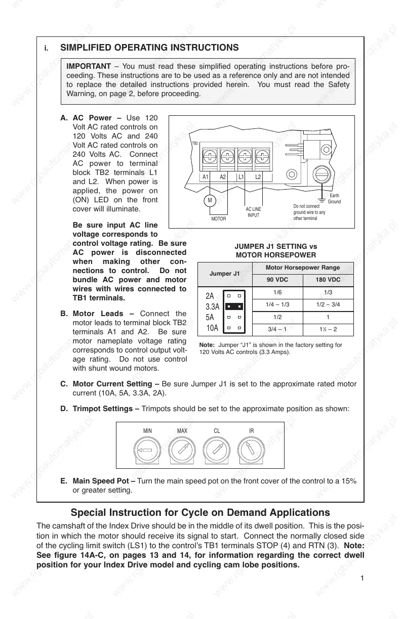
A. AC Power – Use 120
Volt AC rated controls on
120 Volts AC and 240
Volt AC rated controls on
240 Volts AC. Connect
AC power to terminal
block TB2 terminals L1
and L2. When power is
applied, the power on
(ON) LED on the front
cover will illuminate.
Be sure input AC line
voltage corresponds to
control voltage rating. Be sure
AC power is disconnected
when making other con-
nections to control. Do not
bundle AC power and motor
wires with wires connected to
TB1 terminals.
B. Motor Leads – Connect the
motor leads to terminal block TB2
terminals A1 and A2. Be sure
motor nameplate voltage rating
corresponds to control output volt-
age rating. Do not use control
with shunt wound motors.
C. Motor Current Setting – Be sure Jumper J1 is set to the approximate rated motor
current (10A, 5A, 3.3A, 2A).
D. Trimpot Settings – Trimpots should be set to the approximate position as shown:
E. Main Speed Pot – Turn the main speed pot on the front cover of the control to a 15%
or greater setting.
1
1
⁄2 – 2
Motor Horsepower Range
Jumper J1
90 VDC 180 VDC
3/4 – 1
1/6 1/3
1/4 – 1/3 1/2 – 3/4
1/2 1
1
IMPORTANT – You must read these simplified operating instructions before pro-
ceeding. These instructions are to be used as a reference only and are not intended
to replace the detailed instructions provided herein. You must read the Safety
Warning, on page 2, before proceeding.
JUMPER J1 SETTING vs
MOTOR HORSEPOWER
Special Instruction for Cycle on Demand Applications
The camshaft of the Index Drive should be in the middle of its dwell position. This is the posi-
tion in which the motor should receive its signal to start. Connect the normally closed side
of the cycling limit switch (LS1) to the control’s TB1 terminals STOP (4) and RTN (3). Note:
See figure 14A-C, on pages 13 and 14, for information regarding the correct dwell
position for your Index Drive model and cycling cam lobe positions.
Note: Jumper “J1” is shown in the factory setting for
120 Volts AC controls (3.3 Amps).