16
After the control has been set up properly (the jumpers set to the desired positions and the
wiring completed), the start-up procedure can begin. If AC power has been properly brought
to the control, the “ON” and the “STOP” indicators will be lighted. Before initially starting, be
sure the main potentiometer is set to approximately 15% rotation. To start the control, move
the Run-Jog/Stop Switch to the “Run” position and release. The “Stop” indicator should extin-
guish and the motor should rotate as the potentiometer knob is rotated clockwise.
Note: If the motor rotates in the wrong direction, it will be necessary to disconnect the
main AC power and reverse the armature wires. To stop the motor, move the Run-
Jog/Stop Switch to the Stop position. If power is lost the control will not restart,
unless the Run- Jog/Stop Switch is moved to the “Run” position.
X. TRIMPOT ADJUSTMENTS
The control contains trimpots which have been factory adjusted for most applications.
Figures 2A and 2B, on pages 4 and 5, illustrate the location of the trimpots and their approx-
imate adjustment positions. Some applications may require readjustment of the trimpots in
order to tailor the control to exact requirements. (See table 2, on page 4, for range and fac-
tory setting of trimpots.) Readjust trimpots as follows:
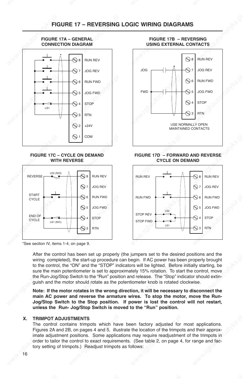
FIGURE 17A – GENERAL
CONNECTION DIAGRAM
FIGURE 17 – REVERSING LOGIC WIRING DIAGRAMS
FIGURE 17B – REVERSING
USING EXTERNAL CONTACTS
FIGURE 17C – CYCLE ON DEMAND
WITH REVERSE
FIGURE 17D – FORWARD AND REVERSE
CYCLE ON DEMAND
*See section IV, items 1-4, on page 9.