Do you have a question about the Camco Vortex 200V and is the answer not in the manual?
Comprehensive safety instructions covering usage, handling, environment, and maintenance.
Explanation of warning symbols and essential safety precautions for amplifier operation.
Guidelines on lightning protection, liquid handling, accessories, connections, volume, and servicing.
Overview of CAMCO's history, expertise, and product philosophy.
Instructions for safely unpacking and checking the amplifier for transit damage.
Detailed specifications and features of the VORTEX power amplifier series.
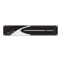
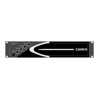
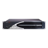
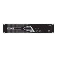
Identification and description of controls and indicators on the front panel.
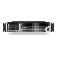
Details of all input, output, and interface connectors on the rear panel.
Initial settings of the amplifier as delivered from the factory.
Information on connecting the amplifier to the AC power source and electrical requirements.
Explanation of the on/off switch and its relation to mains power disconnection.
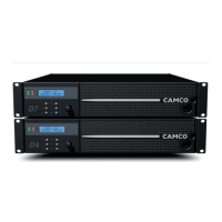
Instructions for securely mounting the amplifier in a standard 19-inch equipment rack.
Ensuring adequate airflow for optimal performance and preventing overheating.
Description of the ground lift switch for preventing ground loops.
Details on activating future software-based features.
Explanation of the yellow LEDs indicating the amplifier's operating mode.
How to change the amplifier's operating mode via the rear panel switch.
Wiring details for balanced XLR inputs, including pin assignments and cable types.
How to connect speakers for independent stereo channel operation.
Connecting speakers for parallel-mono mode, combining channels for increased current.
Connecting speakers for mono-bridge mode, doubling voltage and impedance.
Pin configuration for SPEAKON connectors and proper wiring for mono-bridge.
Overview of controls on the amplifier's front panel.
Using the volume controls for level adjustment and CAI address setting.
Setting the input gain to 26 dB, 32 dB, or 1.4 V sensitivity.
Configuring the clip and speaker protect limiter modes.
Table detailing input sensitivity for different gain settings and loads.
Interpreting the On LEDs for normal operation and various states.
Understanding the green signal LEDs indicating output voltage levels.
Interpreting the bi-coloured clip LEDs for signal clipping and load conditions.
How the clip limiter reduces signal to prevent distortion.
Protection against low load impedance or short circuits.
Ensuring power transistors operate within Safe Operation Area.
Limiting output to protect speakers, with option to disable.
Detecting and preventing DC voltage at outputs; DC servo for signal path integrity.
Monitoring and limiting output current and heat sink temperature.
Managing current surge upon power-on.
Automatic shutdown if mains voltage exceeds safe limits.
Handling mains interruptions and fuse status monitoring.
Monitoring and protecting the Switched Mode Power Supply.
How the temperature-dependent cooling fans operate.
Instructions for removing and cleaning the air intake filter.
Description of the E.U.I.2 for system parameter access and control.
Overview of the CAI bus system for monitoring and remote control.
Guidelines for connecting the VORTEX to a CAI system.
Procedure for setting the CAI address using front panel controls.
Interpreting the green LED that indicates PC communication.
Guide to understanding LED patterns indicating amplifier status and faults.
Diagnosing and resolving problems related to lack of audio output.
Troubleshooting issues with channel separation and distorted audio output.
Identifying and fixing causes of hiss and audio feedback.
Details on the warranty period, coverage, and items not covered.
Procedure for requesting warranty service and product improvement policy.