Do you have a question about the Camco Vortex 4 and is the answer not in the manual?
Covers reading the manual, heeding warnings, and following all instructions for safe amplifier operation.
Advises on avoiding water, damp locations, and proper cleaning methods using only dry cloth.
Details on ventilation, avoiding heat sources, and protecting the power cord from damage.
Guidelines for amplifier usage, placement, power disconnection, and referring servicing to qualified personnel.
Explanation of safety symbols like lightning flash for voltage hazards and exclamation mark for important instructions.
Information on environments, ventilation, water avoidance, cleaning, and power-cord protection.
Guidance on unplugging during lightning storms and ensuring accessible power plugs for safety.
Instructions on avoiding objects, liquids, unstable surfaces, and proper connection procedures.
Emphasis on professional servicing, avoiding self-repair, and using authorized replacement parts.
Introduction to CAMCO's history, expertise in professional sound reinforcement, and commitment to quality.
Instructions for inspecting the amplifier upon arrival, handling shipping damage, and proper repacking for transport.
Details the power output specifications for VORTEX models and highlights microprocessor benefits like reduced distortion.
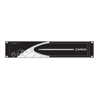
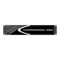
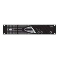
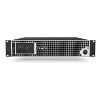
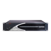
Identifies and describes the controls and LEDs located on the front panel of the VORTEX amplifier.
Details the various input/output connectors, power cable, and rear panel switches for amplifier configuration.
Outlines the factory settings for the VORTEX amplifiers, including front and rear panel configurations.
Provides guidelines for connecting the amplifier to the AC mains supply and understanding power requirements.
Explains the function of the On/Off switch, noting it does not disconnect mains power and automatic restart behavior.
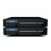
Details the procedure for mounting the amplifier in a standard 19-inch rack using screws and washers.
Discusses the amplifier's cooling system, airflow needs, and requirements for enclosed installations.
Explains the input ground lift switch for preventing ground loops, noting it doesn't affect speaker or mains ground.
Describes the optional feature selector, activated by future software versions.
Details the function of the front panel LEDs that indicate the amplifier's operating mode (Stereo, Parallel-Mono, Mono-Bridge).
Explains how the rear panel mode selector changes the amplifier's operating mode after a restart.
Provides pinout information for XLR connectors and recommends using balanced shielded cables.
Describes the wiring for stereo operation, where both amplifier channels function independently.
Details parallel-mono wiring, combining channels for increased current capability with reduced minimum impedance.
Explains mono-bridge wiring for increased voltage and current, warning about high output voltages.
Details the pin configuration for SPEAKON connectors for channel A and channel B outputs.
Describes the microprocessor-controlled attenuator for volume and the gain selector for input sensitivity.
Explains the function of the On LEDs, Signal LEDs, and Clip LEDs for monitoring amplifier status.
Details the Signal LEDs indicating output voltage and Clip LEDs showing signal clipping or load conditions.
Introduces protection systems like Clip Limiter, Under Impedance Limiter, and SOA Protection.
Explains Speaker Protect Limiter, DC Protection, and SOA Protection for safeguarding amplifier components.
Details Over Current Protection and Thermal Protection mechanisms that monitor and manage heat and current levels.
Covers mains over voltage detection and mains failure detection features for amplifier protection.
Explains fuse protection, inrush current limitation, and how they safeguard the amplifier from power surges.
Details protections for the Switched Mode Power Supply transformer, including over current and thermal monitoring.
Describes how the cooling fans operate based on temperature, ensuring optimal cooling performance.
Provides step-by-step instructions for removing, cleaning, and reattaching the air filter for maintenance.
Details the E.U.I.2 interface for accessing system parameters, remote control, and customization.
Explains the CAI bus system for monitoring and remote control of amplifier functions via a master PC.
Guides on how to set and store the CAI address for communication between the amplifier and PC.
Describes the green LED indicator for the presence of communication between the PC and the amplifier.
Explains the meaning of various On LED flashing sequences to diagnose operating status and malfunctions.
Addresses issues related to no sound, low volume, or intermittent signal, suggesting checks for connections and settings.
Helps diagnose problems with lack of channel separation or distorted sound, checking wiring, sources, and settings.
Provides methods to eliminate hiss and feedback issues by checking signal sources, processors, and cables.
Presents graphs for gain vs. frequency, phase vs. frequency, and channel separation measurements.
Displays the common mode rejection ratio measurement graph for typical performance.
Shows output impedance vs. frequency and THD+N vs. input voltage graphs.
Presents damping factor and THD+N vs. frequency measurement graphs.
Bar charts illustrating peak power and distortion-limited output power across different impedances for VORTEX models.
Outlines the 3-year warranty period, covered defects, and common exclusions like misuse or unauthorized service.
Instructions on how to initiate a warranty claim, including notification and packaging requirements.
CAMCO's policy on product improvements and how to contact them for clarification or support.
A form to be completed for service requests, detailing owner information, problem nature, and shipping address.
Specifies that only qualified personnel should perform maintenance and outlines safety checks.
States that all legally prescribed rules and procedures must be adhered to during decommissioning.