VORTEX
A
B
Z ≥ 2*Z
min
Output B
Output A
Input
Channel A
Input
Channel B
3 INSTALLATION
USER MANUAL
VORTEX 6, 4, 2.6 and 200V
P.14
USER MANUAL
VORTEX 6, 4, 2.6 and 200V
P.15
zero. This mode is useful when, for example, 3 identical loud speakers are to be
operated with the same power.
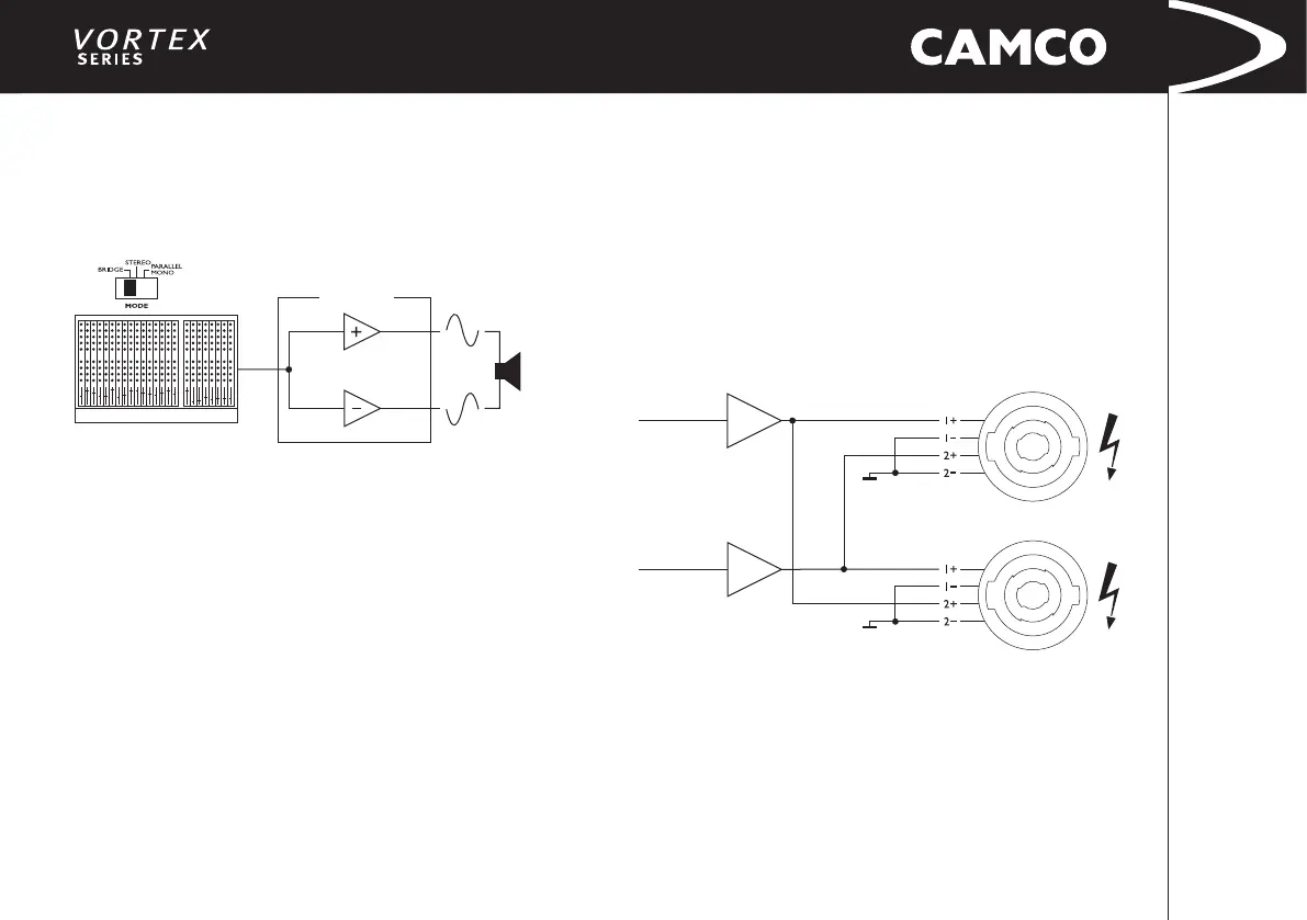
3.9.4 Mono-Bridge Operation
One-channel mono bridged operation.
The second channel processes the same input signal, but with reversed phase.
The (single) load is connected between the two positive channel outputs using
a suitable connected SPEAKON connector. While the total output of the amplier
remains the same, both the available output voltage and the minimum impedance
that can be connected are doubled, as compared with stereo operation. Only
channel A-Input is active – turn the volume on channel B down to zero.
WARNING !
In Mono-Bidge mode RMS output voltages are as high as 230 V. Wiring
to the speaker loads must conform to NEC Class 3 safety standards or its
equivalent that meets all national and local electric codes.
All customer specic cables may only be manufactured by qualied
suppliers/personnel. All cabeling or rewiring work must be carried out by
qualied personnel.
*Z
min
= 2 Ω for VORTEX 6, 4 and 2.6
*Z
min
= 4 Ω for VORTEX 200V
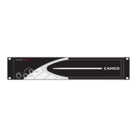
3.9.5 SPEAKON Connection
Both SPEAKON connectors are connected to channel A and channel B outputs.
The pin conguration of the SPEAKON-connectors is as follows:
Upper SPEAKON: Pin 1+ Channel A signal
Pin 1- Channel A ground
Pin 2+ Channel B signal
Pin 2- Channel B ground
Bottom SPEAKON: Pin 1+ Channel B signal
Pin 1- Channel B ground
Pin 2+ Channel A signal
Pin 2- Channel A ground