Do you have a question about the Camco Vortex 6 and is the answer not in the manual?
Instruction to read the user manual for safe operation.
Guidelines for environmental conditions for amplifier use.
Ensuring proper airflow for amplifier cooling and operation.
Safety advice regarding water and moisture exposure.
Instructions for safely cleaning the amplifier.
Guidance on protecting the power supply cord.
Protecting the amplifier from lightning and power surges.
Preventing objects or liquids from entering the amplifier.
Proper placement of the amplifier with accessories.
Safety precautions when connecting equipment.
Advice on setting volume to prevent damage.
Conditions requiring professional servicing.
Instructions on who should service the amplifier.
Ensuring correct replacement parts are used.
Ensuring proper operation after service.
Introduction to CAMCO and its history in sound reinforcement.
Instructions for safely unpacking and inspecting the amplifier.
Overview of the VORTEX amplifier's features, power output, and technology.
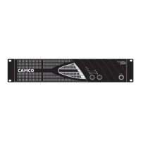
Description of controls and indicators on the front panel.
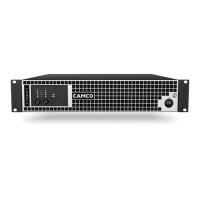
Description of rear panel connectors and features.
Details of the amplifier's default factory settings for front and rear panels.
Requirements and guidelines for connecting the amplifier to AC power.
Explanation of the amplifier's power switch functionality.
Instructions for rack mounting and securing the amplifier unit.
Details on the amplifier's cooling system and ventilation needs.
Explanation of the ground lift switch for preventing ground loops.
Information on the optional feature selector.
Description of the LEDs indicating operating modes.
How to use the rear panel mode selector switch.
General guidance on wiring the amplifier.
Details on E.U.I. and XLR cable connections.
Explanation of stereo mode and its wiring.
Explanation of parallel-mono mode and its wiring.
Explanation of mono-bridge mode and its wiring.
Pin configuration and usage of SPEAKON connectors.
Overview of front panel controls including Volume and CAl settings.
Details on rear panel settings like Gain Selector and Limiter Switch.
Table detailing input sensitivity for different gain settings.
Explanation of On, Signal, and Clip LEDs.
Overview of all power amp protection mechanisms.
Details on mains supply and SMPS protection circuits.
Information on cooling fans, filter cleaning, and SMPS protections.
Details on the E.U.I.2 for system parameter access.
Exploring the possibilities and functions of the E.U.I.2.
Overview of the CAI bus system for monitoring and control.
Instructions for wiring the VORTEX to a CAI system.
Procedure for setting the CAI address using volume potentiometers.
Explanation of the green LED indicating CAI communication status.
Interpreting LED flashing patterns for fault diagnosis.
Diagnosing and resolving issues with no sound output.
Diagnosing and resolving issues with low sound output.
Diagnosing and resolving issues with channel separation.
Diagnosing and resolving issues with distorted sound.
Diagnosing and resolving hiss in the audio signal.
Diagnosing and resolving squeals and feedback issues.
Detailed output power specifications for each VORTEX model.
Information on the amplifier's circuitry design.
Specifications for signal-to-noise ratio.
Details on power consumption for different models.
Specifications for frequency response and input impedance.
Details on voltage gain settings and protection circuits.
Specifications for limiter, fan, and ground lift features.
Information on input/output connectors and operating modes.
Details on options, THD+N, SMPTE, and damping factor.
Specifications for the amplifier's dimensions and weight.
Graph showing gain versus frequency response.
Graph showing phase shift versus frequency.
Measurement of channel separation versus frequency.
Measurement of common mode rejection ratio.
Graph showing output impedance versus frequency.
Graph showing damping factor into 8 Ohm load.
Graph showing THD+N versus input voltage at 1 kHz.
Graph showing THD+N versus frequency at 10 dB below clip.
Measurement of CCIF difference frequency distortion.
Measurement of SMPTE intermodulation distortion.
Bar chart showing peak and distortion-limited output power.
Bar chart showing peak and distortion-limited output power.
Bar chart showing peak and distortion-limited output power.
Bar chart showing peak and distortion-limited output power.
Overview of the VORTEX amplifier's warranty coverage.
Items and conditions not covered by the warranty.
What CAMCO will do to rectify defects under warranty.
Procedure for requesting warranty service.
CAMCO's policy on product improvements.
Definition of qualified personnel for servicing the amplifier.
Guidelines for regular safety checks on the amplifier.
Adherence to rules and procedures for decommissioning.