Vrms
-120
-20
-110
-100
-90
-80
-70
-60
-50
-40
-30
dB
100u 5200u 500u 1m 2m 5m 10 m 20m 50m 100m 200m 500m 1 2
Hz
dB
20 10k50 100 200 500 1k 2k 5k
-120
-20
-110
-100
-90
-80
-70
-60
-50
-40
-30
Hz
Ω
Hz
0
1000
200
400
600
800
damping factor
8 MEASURMENTS
USER MANUAL
VORTEX 6, 4, 2.6 and 200V
P.30
USER MANUAL
VORTEX 6, 4, 2.6 and 200V
P.31
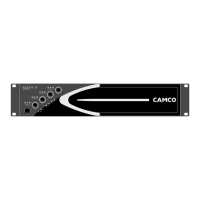
Figure 8.6
THD+N @ 1 kHz, 4 Ω vs. input voltage (Ch1, Ch2)
(Measurements of a typical performance of a VORTEX 6)
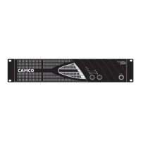
Figure 8.8
THD+N vs. frequency (BW 22 kHz), 10 dB below clip, 4 Ω (Ch1, Ch2)
(Measurements of a typical performance of a VORTEX 6)
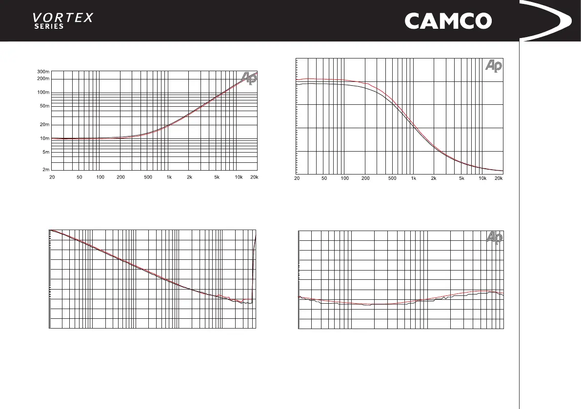
Figure 8.5
Output impedance vs. frequency @ 1 Amp RMS injected current (Ch1, Ch2)
equivalent 11 mΩ + 2,1 uH
(Measurements of a typical performance of a VORTEX 6)
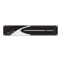
Figure 8.7
Damping factor into 8 Ω (Ch1, Ch2)
equation: damping factor = loaded impedance / amplier output impedance
(Measurements of a typical performanceof a VORTEX 6)