Do you have a question about the CAMDEN CM-120wV2 and is the answer not in the manual?
Procedure to enter programming mode using the Master Code and star key.
Configure fixed or variable length for user codes and the terminator key.
Configure an alarm after a specified number of invalid code entries.
Ensures each user code entered is unique.
Enable or disable anti-tailgating for immediate relocking upon door closure.
Allows User #2 to globally enable/disable access for other users.
Select how relays are allocated: Relay 1 only, split, or sequenced.
Step-by-step guide to add or modify user numbers and their codes.
Procedure to remove a specific user code from the system.
Instructions on how to change the Master User Code.
Set the duration Relay 1 remains active or in toggle mode.
Configure the delay before open door contacts trigger an alarm.
Set the duration Relay 2 remains active or in toggle mode.
Set the delay before Relay 2 activates in sequence mode.
Configure how the incorrect code alarm is announced (buzzer, relay 2, or both).
Enable or disable the alarm for a key being held down too long.
Configure how the door prop open alarm is announced.
Configure lockout after multiple incorrect code entries.
Configure how the door forced open alarm is announced.
Steps to set the announcement method for forced open alarms.
Select Wiegand output protocol: disabled, 26b raw, or 26b raw with facility code.
Set the facility code for 26-bit Wiegand output.
Instructions on using the reset jumper to restore the Master Code.
Procedure to perform a full factory reset, clearing all programming.
| Type | Keypad |
|---|---|
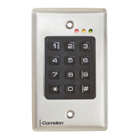
| Model | CM-120wV2 |
| Number of Keys | 12 |
| Number of Codes | 100 |
| Weather Rating | IP65 |
| Connectivity | Wired |
| Color | Silver |
| Power Supply | 12V DC |
| Operating Temperature | -20°C to 50°C |
| Mounting | Surface Mount |
| Relay Contacts | 1 |
| Construction | Metal |
| Material | Zinc |