Page 6 of 15
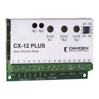
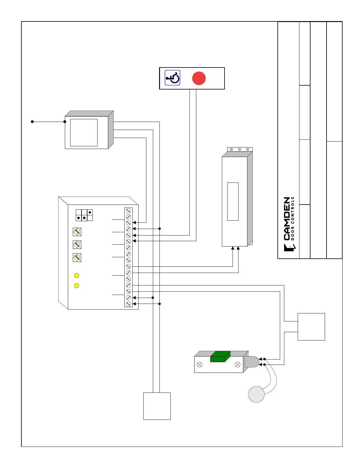
CX-12 PLUS DOOR INTERFACE RELAY
INSTALLATION INSTRUCTIONS
FILENAME: CX-12PLUS-Diagram1.ai
DRAWING No: DRG-CX-12PLUS-01
CX-12PLUS Application Diagram (typical Momentary Operation)
SCALE: NONE
DRAWN BY: DGW REVISED: 1/28/2020DATE: 11/16/09
5502 Timberlea Blvd.
Mississauga, Ontario
L4W 2T7
12/24 V
AC/DC
Power
Wet Input
(ie. Radio Receiver)
Dry Input
(ie. Push Switch)
Electric Strike
Door Operator
Wire MOV
(supplied)
directly to strike
or magnet
Power
for Strike
Radio
Receiver
3 -Term
24V
Com
Radio
1 52 3 4 6 7 8 9 10 11 12 13 14 15 16
RL1 RL2
DRY2WET2DRY1WET1POWER
NO
NO
NC
NC
COM
COM
Relay2Relay1
DOR
RL1
DOO
RL2
DOR
RL2
OFF / ON
1
2
CX-12 PLUS
3
+
-
MOV
CAMDEN DOOR CONTROLS
 Loading...