ENG
The data and information reported in this installation manual are susceptible to change at any time and without obligation to notify users.
Pag.
4 - Manual code:
119 R V16 ver.
1.5 01/2011 © CAME cancelli automatici s.p.a.
“IMPORTANT INSTALLATION SAFETY INSTRUCTIONS”
WARNING: IMPROPER INSTALLATION MAY RESULT IN
SERIOUS DAMAGE. FOLLOW ALL INSTRUCTIONS IN THIS
INSTALLATION MANUAL.
THIS MANUAL IS INTENDED ONLY FOR PROFESSIONAL
INSTALLERS AND OTHER COMPETENT PERSONS.
Technical features
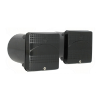
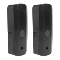
Product description
Pair of infrared-beam photocells with range of up to 20 m – guaranteed
to work in any weather conditions.
Compatible with the DOC series.
DELTA E = Features body and circuitry housed within a container
that is fully external to the anchoring post.
Overall dimensions 70 x 70 x 36 mm.
DELTA I = Features body and circuitry housed within a container
fi tted into the wall requiring masonry work, or inserted into metal
pillars or on support DOC-L posts.
Overall dimensions 70 x 70 x 16 mm.
Item composition
❶ - DELTA -E container base
❷ - DOC-S container for DELTA-I
❸ - DELTA-I container base
❹ - Delta series front-piece
❺ - TX/RX electronic circuit board
❻ - DELTA-E electronic board securing screws
❼ - Screws*+OR base anchoring
❽ - Front-piece securing screw
❾ - Threading for PG7-type male cable gland, added to the
casing base
* DELTA-E: screws not supplied; to choose depending on the type
of anchoring (ø = 4 mm max).
Installation
Before installing, do the following:
• Make sure that the main current is cut off.
• Check that the spot where the equipment will be secured
is protected from possible impacts, and that the surfaces are
sturdy, and that the screws and wall plugs used are suitable
for the job.
• Set up proper tubing and ducts to run through electrical cable.
Mounting instructions
DELTA-E fi gure - Perforate ⓐthe container bases ❶ from the
back so that cables and suitable bolts depending on the chosen
type of support posts can pass through; secure ⓑ nd then the
bases (also using the supplied ❼ Ors), position at the same height
Infrared wavelength
880 nm
Range
20 m
Power supply
12/24V AC/DC
Relay contact rating
500 mA max a 24V
Power draw
110 mA - 24V AC
Protection rating
IP54
Insulation class
III
Working temperatures
-20° ÷ 55°
Material:
Glass fi lled nylon