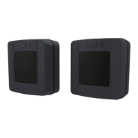
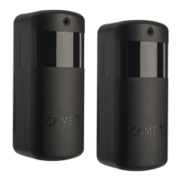
The CAME 806TF-0080 DLX30CEP is a pair of synchronized infrared photocells designed for outdoor use, operating on a 12-24 V AC-DC power supply. These photocells are specifically engineered to detect obstacles and ensure safety in automated gate and door systems. The system comprises a transmitter (TX) and a receiver (RX) unit, which communicate wirelessly via infrared signals. The synchronized nature of these photocells ensures reliable operation and reduces the likelihood of false detections.
Technical Specifications
- Power Supply: 12 - 24 V AC-DC
- Absorbed Current: 40 mA
- Maximum Contact Voltage: 30 V
- Operating Temperature: -20 ÷ +55 °C
- Storage Temperature: -25 ÷ +70 °C
- Protection Rating (IP): 54 (dust and splash water protection)
- Average Life (Cycles): 100,000
- Range: 30 m
Function Description
The 806TF-0080 DLX30CEP photocells function by emitting an infrared beam from the transmitter (TX) and receiving it with the receiver (RX). When an object interrupts this beam, the receiver detects the interruption and signals the control board of the automated system. This signal triggers a safety action, such as stopping or reversing the movement of the gate or door, preventing potential collisions and ensuring user safety. The synchronization between the TX and RX units helps to filter out interference from other light sources, enhancing the reliability of detection.
The device's components include:
- Front cover: Protects internal components.
- Control board: Houses the electronic circuitry for signal processing.
- Front frame: Provides structural support.
- Fixing screws and plugs (non supplied): Used for mounting the device.
- Adhesive ring: For mounting the device.
- External casing: Encloses the entire unit.
- External gasket: Provides a seal for weather protection.
Usage Features
The photocells are designed for easy installation and configuration. The RX unit features a control board with several indicators and DIP switches for setting up the device.
RX Unit Features:
- LED Indicators:
- RX-TX alignment (LED 1): Indicates the quality of the alignment between the RX and TX units.
- 1 flash per second: Weak alignment
- 2 flashes per second: Sufficient alignment
- 3 flashes per second: Good alignment
- 4 flashes per second: Excellent alignment
- Active output on RX signal (LED 3): Indicates the status of the output.
- On: Output idle
- Off: Output active
- DIP Switches (1-2-3): Used to set the addresses for each pair of photocells.
- Jumper: For setting the type of output contact on RX (default: NC contact).
- Power supply terminal board: For connecting the power supply.
- Jumper: For setting the transmission range (default: 30 m).
- DIP Switch (4): For setting the obstacle recognition sensitivity.
- OFF: Maximum sensitivity (max. 4 pairs of synchronized photocells).
- ON: Normal sensitivity (5-8 pairs of synchronized photocells).
- SY terminal: Used when there are 3 or more pairs of photocells (max. 8 pairs).
TX Unit Features:
- LED Indicator (LED 7): Indicates the operation of the TX unit.
- Slow flash: TX2-TX8 connected to TX1 with terminal SY.
- Quick flash: TX2-TX8 not connected to TX1 with terminal SY.
- The TX1 photocell transmitter always flashes slowly.
Connections and Settings:
- Connecting a pair of photocells: Connect the TX and RX units to the control board.
- Connecting two pairs of photocells: Follow the wiring diagram for multiple pairs.
- Connecting multiple pairs of photocells (max. 8): The system supports up to 8 pairs of photocells, allowing for comprehensive safety coverage.
- Connecting the SY terminals on the TX photocells together: This is crucial for synchronized operation when multiple TX units are used.
- Test Function: If the services test function has been set on the CAME control panel, connect the TX photocells to terminals 10 and TS, instead of 10 and 11, on the control panel.
- Output Contacts: For the OUT output contacts, always check the connection and function instructions in the relevant CAME control panel manual.
- Different Photocell Types: For installations alongside photocells of a different type, it is recommended to install TX transmitters and RX receivers alternately, as shown in the provided figures.
Function of the DIP Switch:
- Address Setting: On TX and RX, use DIP-switch (1-2-3) to set the address for each pair of photocells. For the first pair of photocells (RX1-TX1), all DIP-switches must be set to OFF.
- Obstacle Recognition Sensitivity: On TX, use DIP-switch (4) for setting the obstacle recognition sensitivity.
- OFF: Maximum obstacle sensitivity (max. 4 pairs of photocells synchronized).
- ON: Normal sensitivity (5-8 pairs of photocells synchronized).
- Interference Prevention: In mixed installations with other types of photocells, set the sensitivity lower (DIP-switch 4 to ON) to prevent the photocells from interfering with one another.
Maintenance Features
The device is designed for durability and minimal maintenance.
- Environmental Conditions: Before installing the product, keep it at room temperature where it has previously been stored or transported at a very high or very low temperature.
- Regular Checks: The average product life is a purely indicative estimate. It applies to compliant usage, installation, and maintenance conditions. It is also influenced by other factors, such as climatic and environmental conditions.
- Cleaning: Regularly clean the external casing to ensure optimal performance and prevent dust or debris from obstructing the infrared beam.
- Wiring Inspection: Periodically inspect all wiring connections for tightness and integrity to ensure reliable operation.
- Power Supply: Ensure the power supply voltage is within the specified range (12-24 V AC-DC) and that the supply current does not exceed 500 mA.
- Always ensure that the product is installed by qualified personnel in compliance with local regulations and safety standards.
- Wear anti-static clothing and footwear if performing work on the circuit board.
- Only use this product for its intended purpose. Any other use is hazardous.
- The manufacturer cannot be held liable for any damage caused by improper, unreasonable or erroneous use.
- Always check the warnings in the installation and use manuals for the operator the product is associated with.
- Make sure the mains power supply is disconnected during all installation procedures.
- This product complies with the applicable standards in force at the time of manufacturing.
- The product, in its original packaging supplied by the manufacturer, must only be transported in a closed environment (railway carriage, containers, closed vehicles).
- If the product malfunctions, stop using it and contact customer services at https://www.came.com/global/en/contact-us or via the telephone number on the website.
- The manufacturer data is provided in the production batch printed on the product label. If necessary, contact us at https://www.came.com/global/en/contact-us.
- The general conditions of sale are given in the official CAME price lists.
- If the device is not powered by a CAME control panel, make sure that the supply voltage to the device has a current limiter of no more than 500 mA.
Disposal and Dismantling:
Dispose of the packaging and the device responsibly at the end of its life cycle, in compliance with the laws in force in the country where the product is used. The recyclable components are marked with the material symbol and ID. The data and information in this manual may be changed at any time and without notice. Measurements are in millimeters, unless stated otherwise.