EasyManua.ls Logo

CAME SMA - User Manual

CAME SMA
4 pages
Print Icon
To Next Page IconTo Next Page
Loading...
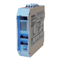
SMA/SMA 2/ SMA 220 loop detector DIN variant, mounting rail installation
LCD display
«Mode» button
«Data»-button
Terminals
Info LED
1
Loop detector for industrial doors and gates,
car parks and parking bollards
2
Mechanical mounting in the switch cabinet
3
Electrical connection
Terminal connection diagram
Translation of the original instructions
Safety instructions
1
General
These devices and their accessories may only be operated in compliance with the operating instructions (intended use)!
These devices and their accessories may only be commissioned by trained and qualified personnel.
These devices may only be operated with the intended operating voltages and parameters.
If malfunctions occur that cannot be rectified, shut down the device and send it in for repair.
These devices are only allowed to be repaired by the manufacturer. Tampering and alterations are not permitted. This will invalidate all guarantee and
warranty claims.
The SMA / SMA 2 / SMA 220 is mounted on a 35 mm mounting rail acc. to EN 50 022 in the switch cabinet.
The terminals are pluggable and coded.
A:
Supply
voltage
connection
B:
Loop connection
1-channel device
C:
Loop connection
2-channel device
D:
Alarm output
connection
(optional)
E:
Relay connection
output 1
F:
Relay connection
output 2
AC
AC
A1
A2
31
32
34
no
nc
common
14
11
12
no
nc
common
24
21
22
n
o
nc
common
L3
L4
L3
L4
L5
L6
1
2
The loop connection wiring to the loop detector must be twisted at least 20 times per meter.
Please ensure the unit is wired properly with correct input voltage and all terminals are connected according to the wiring diagram on the label.
1-loop device
Relay assignment:
Output connection
diagram:
Output 1 E
Output 2 F
Alarm output D
2-loop device
Relay assignment:
Output connection
diagram:
Output 1+2 E, F
Alarm output D
Output connection options (depending on the options ordered):
3.1
ENGLISH
General
Explanation of the LCD display Explanation of the LED
Standard display
1-loop device
Standard display
2-loop device
Control button Control button
1
1
2
Mode
Sim1
Data
Sim2
1
2
Loop 2
Example:
Parameter «h»
set
Function
Example:
Time
function set
Loop 1
Red + green: Start-up phase
Green: Operation
Red + green: Configuration
Flashing green: Output 1 and/or
2 activated
Flashing red: Error
Flashing
red + green: Simulation
The settings of the devices in this chapter are shown and explained for the 1-loop device. The settings for loop 2 of a 2-loop device should be made using
the corresponding method.
4
Value and parameter setting options
LCD display and controls
4.1
SMA - SMA2 - SMA220

Other manuals for CAME SMA

Questions and Answers

  • C
    Colin BrooksAug 15, 2025
    What does error E001 mean on CAME Security Sensors?
    • A
      angela98Aug 15, 2025
      If your CAME Security Sensors display error E001, it indicates an interruption in Loop 1. Briefly pressing the «Data» button shows the last of 4 errors on the display.
  • J
    Julie RossAug 18, 2025
    What does error E002 mean on CAME Security Sensors?
    • A
      Amanda MillerAug 18, 2025
      If your CAME Security Sensors display error E002, it indicates an interruption in Loop 2. Briefly pressing the «Data» button shows the last of 4 errors on the display.
  • C
    Christian VazquezAug 21, 2025
    What does error E011 mean on CAME Security Sensors?
    • B
      Brooke FergusonAug 21, 2025
      If your CAME Security Sensors display error E011, it indicates a short circuit in Loop 1. Briefly pressing the «Data» button shows the last of 4 errors on the display.
  • T
    Tricia DavisAug 25, 2025
    What does error E012 mean on CAME Security Sensors?
    • U
      unicholsAug 26, 2025
      If your CAME Security Sensors display error E012, it indicates a short circuit in Loop 2. Briefly pressing the «Data» button shows the last of 4 errors on the display.
  • K
    kaylee08Aug 28, 2025
    What does error E301 mean on CAME Security Sensors?
    • A
      Anthony PruittAug 28, 2025
      If your CAME Security Sensors display error E301, it indicates that Loop 1 is too large. Briefly pressing the «Data» button shows the last of 4 errors on the display.
  • A
    Amy BlackAug 31, 2025
    What does error E302 mean on CAME Security Sensors?
    • Q
      qandrewsSep 1, 2025
      If your CAME Security Sensors display error E302, it indicates that Loop 2 is too large. Briefly pressing the «Data» button shows the last of 4 errors on the display.
  • K
    Kari MontgomerySep 3, 2025
    What does error E311 mean on CAME Security Sensors?
    • D
      Dr. Leslie ClarkeSep 4, 2025
      If your CAME Security Sensors display error E311, it indicates that Loop 1 is too small. Briefly pressing the «Data» button shows the last of 4 errors on the display.
  • W
    wknightSep 7, 2025
    What does error E312 mean on CAME Security Sensors?
    • L
      Louis HuntSep 7, 2025
      If your CAME Security Sensors display error E312, it indicates that Loop 2 is too small. Briefly pressing the «Data» button shows the last of 4 errors on the display.
  • H
    Holly CaseySep 12, 2025
    What does error E201/E202 mean on CAME Security Sensors?
    • P
      Philip JensenSep 12, 2025
      If your CAME Security Sensors display error E201 or E202, it indicates a saving error. Briefly pressing the «Data» button shows the last of 4 errors on the display.

Summary

Safety Instructions

Mechanical Mounting

Electrical Connection

Terminal Connection Diagram

Diagram illustrating terminal connections for supply, loop, and relay outputs.

Value and Parameter Setting Options

LCD Display and Controls

Explains the LCD display and control buttons for device operation.

Basic Functions and Modes

Details fundamental operational modes and their behavior.

Time and Sensitivity Settings

Covers time functions, sensitivity adjustment, and automatic boost.

Frequency, Direction, and Output Settings

Explains frequency, direction logic, and output 2 configuration.

Power Failure Protection and Configuration Entry

Describes power failure protection and how to enter configuration mode.

Configuration Mode Parameters

Detailed settings for various functions within the configuration mode.

Simulation Mode

Troubleshooting

Reset Functions

Technical Data

CAME SMA Specifications

General IconGeneral
BrandCAME
ModelSMA
CategorySecurity Sensors
LanguageEnglish

Related product manuals