Safety instructions
1
These devices and their accessories may only be operated in compliance with the operating instructions (intended use)!
These devices and their accessories may only be commissioned by trained and qualified personnel.
These devices may only be operated with the intended operating voltages and parameters.
If malfunctions occur that cannot be rectified, shut down the device and send it in for repair.
These devices are only allowed to be repaired by the manufacturer. Tampering and alterations are not permitted. This will invalidate all guarantee and
warranty claims.
The loop connection wiring to the loop detector must be twisted at least 20 times per meter.
Please wire the device in accordance with the terminal assignment. Make sure the terminals are assigned correctly.
1
L
OOP DETECTOR
Documentazione
Tecnica
T20
r
ev. 3.0
0
1/2010
©
CAME
CANCELLI
AUTOMATICI
119RT20-EN
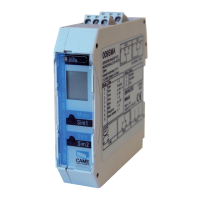
SMA - SMA 2 - SMA 230
ENGLISH
Operating instructions for Installing and Start-up (Translation)
Mounting and electrical connection
SMA is mounted directly onto a standardized 35-mm mounting rail.
The terminals for all connections are coded pluggable terminals.
2
Supply voltage
Loop connection
1-channel device
Loop connection
2-channel device
Alerting Output 2nd output
Relay response to malfunctions (see chapter 6 Troubleshooting):
General
Explanation of the LCD display
Explanation of the LED
Standard display
1-loop device
Standard display
2-loop device
Control button Control button
Loop 2,
output 2
Example:
Parameter «h»
set
Function
Example:
Time
function set
Loop 1, output 1
Red: Start-up phase
Green: Operation
Red & green: Configuration
Flashing green: Loop activated
Flashing red: Error
Flashing red + green: Simulation
The settings of the devices in this chapter are shown and explained for the 1-loop device. The settings for loop 2 of a 2-loop device should be made using
the corresponding method.
1.Door/gate
systems
A malfunction causes
the output relay to be
released. The alarm
relay drops out.
2. Barrier
A malfunction causes
the output relay to pick
up. The alarm relay
drops out.
3. Quiescent
current
A malfunction causes the
output relay to be
released. The alarm relay
drops out.
4. Direction logic
(2-loop device
only)
A malfunction causes
the output relays to be
released. The alarm
relay drops out.
Parameters
1: Door and gate The assigned output relay picks up when the loop is activated and drops out when the loop returns to a non-activated condition.
2: Barrier The assigned output relay picks up when the loop is activated and drops out when the loop returns to a non-activated condition.
3: Quiescent current The assigned output relay drops out when the loop is activated and picks up again when the loop returns to a non-activated condition.
4: Direction logic Output 1 switches if an object moves from loop 1 to 2. Output 2 switches if an object moves from loop 1 to 2. Both loops must be
activated for a short time. The outputs are reset again when loop 2 returns to a non-activated condition. Both loops must have re-
turned to a non-activated condition for another direction detection.
0: Loop 2 Loop 2 / output 2 can be deactivated in a 2-loop device.
3
Value and parameter setting options
LCD display and controls
3.1
Basic functions 0 (see Table 4.1a for settings)
3.2