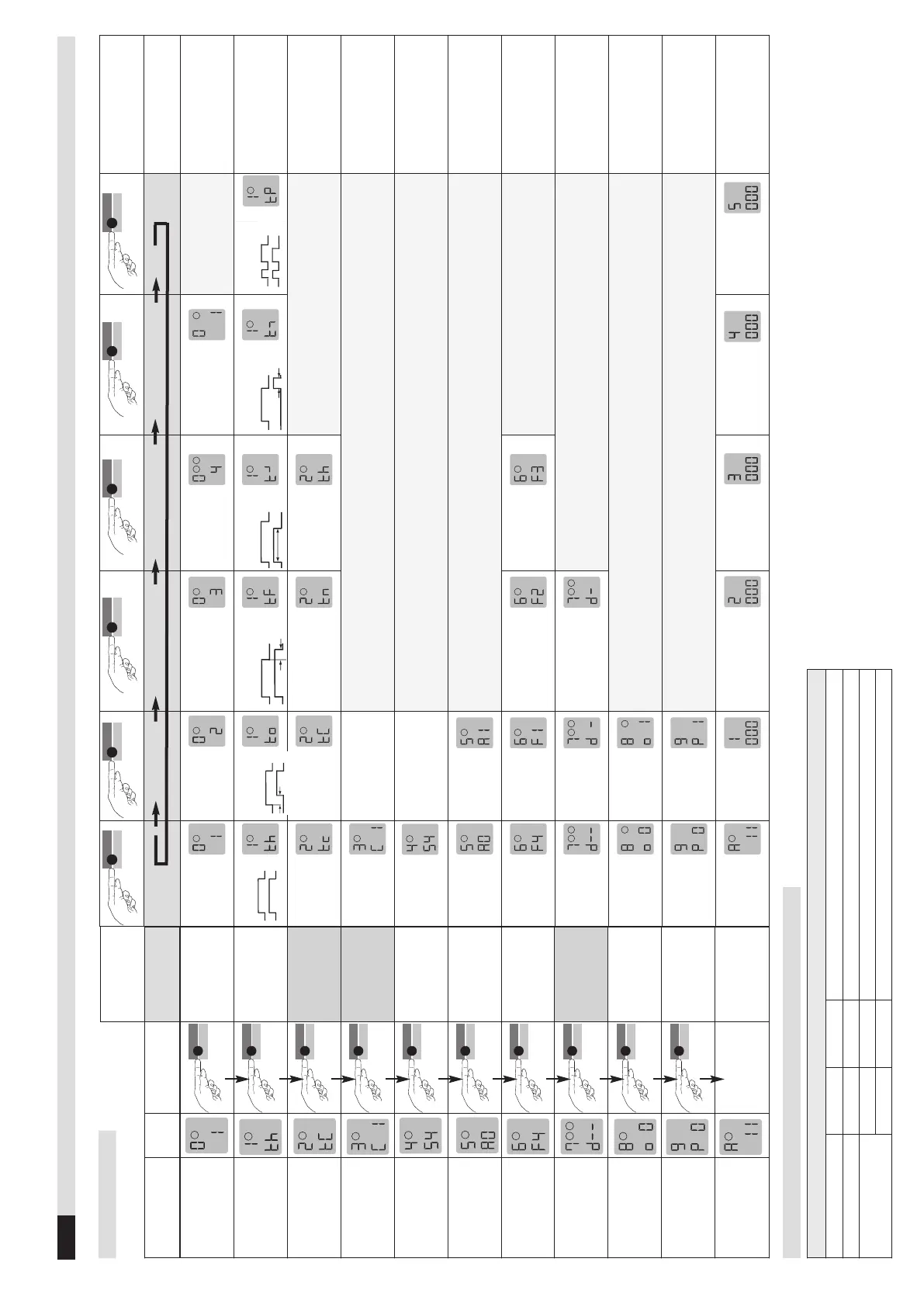
Function
LCD
display
Button operation
functions
0 - Basic function
1 - Time function
2 - Time unit
This display does
not appear with
time function th (∞)
3 - Time factor
This display does
not appear wih time
function th (∞)
4 - Sensitivity
5 = Sensitivity
5 - Automatic
Sensitivity Boost
ASB
ASB stands for
Automatic Sensiti-
vity Boost
6 - Frequency
7 - Direction logic
This display appears
only with a
2-loop device
8 - Output 2
configuration
9 - Protection
against power
failure
A - Operating
mode
3
Notes
Door/gate
systems*
Barrier systems
Quiescent current
Direction logic
Only 2-loop device:
Loop 2
activated: «1»*
deactivated: «0»
With deactivation of Loop 2
the output 2 becomes
configurable g 8
∞*
On delay
Off delay
Activation
pulse loop
Time funct. pulse
when loop is exited
Max. presence
0.1 second
1 second*
1 minute
1 hour
The time unit multiplied by
the time factor gives the
set time.
1*
Set value between 1
and 99 by touching or
holding the «Data»
button
4*
Set value betw. 1 (lowest
) and 9 (highest sensi.)
by touching or holding
the «Data» button
Setting restrictions:
rotection against power
failure (with P1): Value 1-5
Switched off*
Switched on
Frequency F4*
Frequency F1
Frequency F2
Frequency F3
Both directi-
ons*
Loop 2 to loop
1
Loop 1 to loop 2
The direction logic function
can only be implemented
with 2 loops and a 2-loop
device
Output 2 is
switched off
Output 2 is
activated
Loop 2 has to be
deactivated «0»
Switched off*
Switched on
If parameter 9 = P 1
parameter 5 must be set to off
(5 = A0 ).
Operating
mode
Error memory
slot 1
Error memory slot 2
Error memory
slot 3
Error memory
slot 3
Error memory
slot 5
Possible displays in case of
error: see chapter 6 of these
operating instructions
Button operation
parameter
4.11
Configuration mode
Table 4.1a Settings
Table 4.11b Different product variants (setting options)
*
F
ac
tory
s
etti
ng
Note on 2-loop device: After loop 1 has been set, the parameters for loop 2 are set (make the settings using the same procedure) and the settings are not shown in the table with the exception of the direction logic
SMA/SMA 2/ SMA 220
Output 2
Notes
1-loop device, 2 relays
–
1*/0
1 = Output 2 on; 0 = Output 2 off
2-loop device, 2 relays
active
–
Parameter 8 is not possible and is not displayed
deactivated
1/0*
1 = Output 2 on; 0 = Output 2 off
 Loading...