Do you have a question about the Cameron CLIF MOCK CD-20SFA and is the answer not in the manual?
Defines symbols and terms used for warnings and cautions in the manual.
Explains the operational principle of the CD-20SFA controller and its components.
Details the product's UL listing and compliance for hazardous locations.
Provides instructions for physically mounting the controller and making electrical connections.
Outlines procedures to isolate operational problems using basic equipment.
Steps to verify the basic functionality of the CD-20SFA controller.
Procedures to check the combined operation of the sample probe and controller.
Explains the functions of the control card and power board components.
Lists common problems, their probable causes, and recommended solutions.
Guidelines for product repairs and the implications for UL certification.
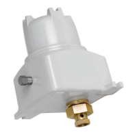
The CD-20SFA Sample Probe Controller is a device designed for the pulse input (flow proportional) control of True-Cut C-Series sample probes. Its primary function is to rotate the sample probe to capture and discharge an isokinetic sample upon receiving a "start" pulse. When installed in a horizontal line, the probe stops in the closed position, while on a vertical line, it stops in the open position.
The controller operates by receiving an input pulse from an external source, which triggers the motor to rotate the probe. Armature feedback regulates the motor speed to approximately 12 rpm, and current feedback limits the motor current to 3 amperes. The pulse input must be closed for at least 5 milliseconds to generate a "start" pulse, and an electronic square wave input requires an amplitude of 12VDC. A proximity switch input amplifier provides the signal to stop the motor. Two LEDs on the controller card, I-LIMIT and PROX ("Hold"), indicate the drive's current limit status (normal during acceleration) and when the motor is stopped, respectively. The PROX ("Hold") LED illuminates when a high point on the cam is opposite the proximity switch, signaling the "stop and hold" position of the sample probe.
The CD-20SFA also features a failure alarm relay that provides an output to alert users to a loss of power, loss of input signal, or motor failure. This relay contact remains open (inactive) as long as a sample is being taken within the configured alarm delay period, which can range from 5 seconds to 6 minutes. The device is housed in an explosion-proof enclosure with two ¾-inch NPT holes for line power and input pulse connections, and a ½-inch breather plug and a ½-inch conduit plug on opposite sides. It mounts directly to the C-Series sample probe using a coupling, jam nut, and hub, eliminating the need for additional brackets or supports, though they are recommended for installations with significant vibration.
The CD-20SFA controller is available in 24VDC, 115VAC, and 230VAC input power versions.
| Brand | Cameron |
|---|---|
| Model | CLIF MOCK CD-20SFA |
| Category | Controller |
| Language | English |