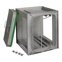
The Camfil FB-Series Fluid Seal Bag-in/Bag-out Filter Housing is a containment-design, side-loading filter housing specifically engineered for critical air filtration applications. It is primarily used in industries and research facilities that handle dangerous or toxic, biological, radiological, or carcinogenic materials, where minimizing exposure to harmful contaminants during filter replacement is paramount.
Function Description
The core function of this filter housing is to provide a secure and contained environment for filtering air contaminated with hazardous substances. The "Bag-In/Bag-Out" design refers to the method of replacing filters, where both new and contaminated filters are handled through a heavy-duty plastic bag attached to an access port. This procedure ensures that personnel are protected from exposure to the contaminants during the change-out process.
The filter-to-housing seal is achieved through a robust mechanism involving two filter locking mechanisms. These mechanisms press the fluid seal channel of the filter against a knife-edge sealing surface within the housing. This creates a positive, airtight seal, preventing any bypass of unfiltered air. The locking mechanism is designed to be operated from inside the housing and prevents the access door from being installed unless the mechanism is properly secured. After initial filter installation or contaminated filter change-out, the system must undergo an in-place leak test to confirm the integrity of the seals and ensure all contaminants are effectively filtered from the air stream.
Camfil's Bag-In/Bag-Out housings are versatile and can be configured in various arrangements to meet specific user requirements and accommodate different types of filters or adsorbers. They are available in multiple sizes, ranging from one-half wide to three-wide housings. These units can function as small, individual filtration systems or be combined as several housing modules. These modules can be factory welded and stacked to create larger, more complex filtration systems, offering flexibility to meet diverse customer needs. Despite variations in size and configuration, the fundamental filter change-out procedure remains consistent across all models.
For multi-wide housings, filter removal rods are incorporated to assist in pulling the second and/or third prefilters and final filters towards the front access port. These rods are operated from inside the change-out bag using glove sleeves. While the first filter is typically removed by hand to reduce the load, the rods facilitate the removal of subsequent filters, especially heavy adsorbers.
The system can also integrate In-Place Test Section housings, which assist qualified testing technicians in performing in-place testing of filters or adsorbers. Camfil offers four types of test sections: upstream, combination, downstream, and accurate scan. The upstream test section ensures uniform dispersion of a challenge agent across the filter/adsorber face and samples the concentration entering the downstream filter/adsorber. The combination test section adds the capability to sample the air stream for leaks that may have bypassed the upstream filter/adsorber. Downstream test sections specifically sample for bypass leaks. The "Accurate Scan" test housing includes a bag-protected access port, allowing scan testing of the downstream face of a HEPA filter from outside the contaminated air stream using a probe with guide rods to ensure comprehensive coverage.
Usage Features
Operating the Camfil FB-Series housing involves several key steps, particularly during installation and filter change-out.
Installation of Filtration Housing:
- Before installation, all loose items stored inside the housing during shipment must be removed, inventoried, and stored in a controlled environment, remaining in their original boxes until needed.
- A minimum of four feet of clearance in front of the access door(s) is recommended for ease of filter installation and change-out.
- The housing must be installed with the correct orientation, ensuring the airflow direction and access door position are appropriate for the system layout.
- Ductwork should be permanently installed and sealed to the housing to prevent leakage. The entire filtration system, including fans and dampers, must be complete and securely mounted to a curb, base, or structural support.
- After ductwork and housing installation, the system should be thoroughly cleaned to remove dust or debris before new filters/adsorbers are installed.
Installation of New Filter(s) or Adsorber(s) Prior to New System Start-Up:
- Verify the correct model number, quantity, type, and size of media.
- Filters/adsorbers are unpacked carefully, resting the filter on the floor, cutting the taped seam of the box, and pulling excess bag(s) over the box edge. The box is then carefully turned over, allowing the filter to rest on the floor, before removing the box and packaging.
- Extreme caution is advised when handling HEPA filters, touching only the exterior frame to avoid damaging the media and affecting performance.
- Visually inspect the filter/adsorber frame and media for any damage before installation.
- Access to the housing interior is gained by removing doorknobs (or loosening and swiveling door bolts for swivel latch models) and pulling the access door straight out.
- Prefilters, if required, are pushed into the housing using the slide track, ensuring pleats are in the vertical position.
- For primary filters/adsorbers, the locking mechanism handle is released and fully opened. Filters/adsorbers are loaded with the fluid seal channel facing the housing knife-edge. Filter clips should be at the top and bottom, with pleats vertical for filters and carbon beds horizontal for adsorbers. Filters/adsorbers are pushed to the back of the housing until they stop. In multi-wide housings, it may be necessary to push one filter as far back as possible, then use a second filter to help push the first. The last filter/adsorber edge should align with the sealing surface.
- Once loaded, the locking mechanism handle is slowly closed towards the handle latch, engaging the fluid seal channel with the knife-edge sealing surface, and then locked.
- Plastic change-out bag(s) are installed over the bagging ring(s), ensuring the correct size and proper orientation of the bag seam and gloves. The shock cord is positioned between the second raised rib of the bagging ring and the housing. A security strap is then installed around the bag, Velcro side out, between the first and second raised ribs of the bagging ring, tightened to prevent interference with the door seal. The bag is extended, folded, and rolled towards the housing to squeeze out trapped air, then tucked neatly between the bagging ring and the filter access port. The access door is then carefully replaced and doorknobs tightened alternately to seal against the housing.
Filter Change-Out (Replacing Contaminated Filters Or Adsorbers):
- Before replacing contaminated filters/adsorbers, airflow through the filtration system must be stopped, either by shutting down the system or bypassing airflow to another system. Upstream and downstream dampers should be closed. Protective clothing, gloves, and respirators are recommended.
- Access to the housing interior is gained by removing the access door.
- To remove filters/adsorbers, the change-out bag is extended. For filters sealed by a locking mechanism, the handle is released and fully opened to disengage the filter from the knife-edge sealing surface.
- One change-out bag is used per filter/adsorber (multiple prefilters can be removed in one bag if weight is under 25 lbs). Arms are inserted into the bag gloves to pull the filter into the bag. A change-out shelf or table can assist. The sealing surface of the housing is inspected for foreign matter.
- Once the filter/adsorber is in the bag, the bag is tightly twisted between the filter access port and the contaminated filter, taped or tied approximately 8" of the twisted bag, cut in the middle, and taped over exposed edges. The contaminated filter/adsorber is then removed for disposal. A banding kit can also be used. The security strap is removed, and the bag's shock cord is positioned between the two raised ribs of the bagging ring.
- For multi-filter systems, a new empty change-out bag is installed over the bagging ring (over the "stub" bag), with the shock cord between the second raised rib and the housing, and the seam at the top. The "stub" bag is removed from the bagging ring and pulled to the bottom of the change-out bag. The security strap is re-installed, and the next filter/adsorber is carefully removed into the change-out bag. This process is repeated until all filters are removed, leaving a "stub" bag on the bagging ring.
- A new change-out bag is placed over a new filter/adsorber, ensuring correct orientation of filter clips. The shock cord is pulled to the bottom of the filter, and the bag is pulled down until the filter is at the back of the bag. The filter/adsorber is turned over, and the bag is pulled up. The new change-out bag with filter/adsorber is installed around the bagging ring (over the "stub" bag), with the shock cord between the second raised rib and the housing, and the seam at the top. An arm is inserted into the glove closest to the housing to remove the "stub" bag from the bagging ring, pulling it into the glove while turning the glove "inside-out." The security strap is reinstalled, and the new filter/adsorber is slid into the housing. Once installed, the change-out bag is tightly twisted between the filter access port and the glove turned "inside-out," taped or tied, cut in the middle, and taped over exposed edges. This process is repeated for all new filters/adsorbers.
- After all filters/adsorbers are installed, the change-out bag is secured with the security strap. The locking mechanism handle is slowly closed to seal the filter/adsorber with the knife-edge sealing surface, and then locked.
- The "stub" bag inside the glove closest to the housing can be removed by twisting, taping/tie strapping, and cutting off (taping over exposed portion). If it doesn't interfere with the access door seal, it can remain inside the new bag. The change-out bag is extended, folded, and rolled towards the housing to squeeze out trapped air, then tucked neatly between the bagging ring and the filter access port. The access door is carefully replaced, and doorknobs tightened alternately to seal against the housing. Upstream and downstream dampers are opened, and the system is restarted.
Maintenance Features
Proper maintenance is crucial for the optimal operation of the filtration housing and to ensure the desired level of filtration is consistently met.
Filter Change-Out Determination:
Filters/adsorbers require change-out when they no longer function properly.
- Particulate Filters (prefilters, HEPA filters): Change-out is needed when the pressure drop across the filter exceeds the recommended change-out pressure or system design pressure, or when the HEPA filter in-place leak test shows unacceptable penetration of challenge aerosol.
- Carbon Adsorbers (HEGA): Change-out is required when the in-place leak test shows unacceptable penetration of the challenge agent.
Filtration System Maintenance:
The filtration system, whether a single housing or a complete filter train, is deemed improperly functioning if:
- Periodic site inspections, routine maintenance checks, or planned surveillance testing reveal torn gaskets, broken welds, stripped threads on door bolts, or any other indication that the system's ability to contain the process airstream has been compromised.
To ensure peak performance, owners must commit to periodic component maintenance, inspections/repairs, and testing performed by qualified In-Place Testing personnel. This safeguards containment and ensures prompt, sufficient repairs.
Component Replacement:
Some damaged components of the filtration system can be replaced.
- Access Door Gaskets: If damaged, door gaskets can be replaced. The procedure involves:
- Removing the door with the damaged gasket (after shutting down the filtration system and consulting safety personnel).
- Carefully removing the old gasket and any remaining adhesive caulking.
- Dry fitting the new gasket to the door, cutting it to length with a 3/4" overlap for compression.
- Applying a continuous bead of adhesive caulking (1/8" to 3/16" diameter) inside the bottom of the extruded gasket channel.
- Placing the gasket on the door, pinching the extruded gasket together, and applying a thin layer of caulking over the cut ends.
- Checking and repositioning the gasket if needed, then applying caulking around the perimeter where the top edge of the gasket meets the door.
- Allowing 24 hours for the adhesive caulking to fully cure before reinstalling the door.
- Removable Fluid Seal Locking Mechanism: If the locking mechanism deteriorates or is damaged over time, it may need replacement. This involves:
- Consulting safety personnel before accessing a housing that has been in service.
- Removing the access door.
- Carefully removing the top locking mechanism to prevent it from falling. The distance of the 3/8" locknuts on the adjustment mechanism is measured for later use. Two 3/8" locknuts from the backside of adjustment studs, two 5/16" locknuts from the pivot arms, the locking handle, and 3/8" locknuts from the locking trays are removed (saving all locknuts for reinstallation).
- Removing the locking mechanisms, ensuring nylon flat washers around each 3/8" stud remain in place.
- Installing replacement locking mechanisms, securing with 3/8" locknuts (tightened then loosened 1/4 turn for free movement of the locking tray). The locking handle is installed by sliding adjustment studs through linkage tabs and pivot arms through 5/16" studs (tightened then loosened 1/4 turn for free movement of the locking handle).
- Tightening 3/8" locknuts on adjustment studs using the previously recorded dimension. The mechanism is opened and closed several times to ensure free movement.
Locking Mechanism Adjustment:
The locking mechanisms are factory preset for correct tension. If the handle requires more than moderate pressure to latch, adjustment is needed.
- Excessive tension: Locate the 3/8" locknuts on the adjustment studs. Turn them counter-clockwise until proper tension is achieved, then tighten the inside nuts.
- Insufficient tension: Locate the 3/8" locknuts on the adjustment studs. Loosen the inside nuts and turn the 3/8" locking nuts clockwise until proper tension is achieved, then tighten the 3/8" locknuts back to the inside nuts.
Camfil also provides various spare parts and accessories, including door gaskets, doorknobs, change-out shelves, banding kits, and doorknob installation ratchet attachments, to facilitate repairs and filter change-out procedures.