EU DECLARATION OF CONFORMITY
The manufacturer CAMLogic declares under its own responsability that the product PFG-86/./././. answers to the requisites
of the European Directive 2014/34/EU in consideration of the standards : EN IEC 60079-0:2018 and EN 60079-31:2014.
00625 97.06 - Rev. 05
SGC2014
ELECTRICAL WIRING
Fig.3
MAINTENANCE
WARRANTY
Instructions Manual No. 00625 97.06 - Rev. 05
The conductors forming the power supply and signal carrying cable must have an adequate cross-section so that
the current density, in each conductor, is no higher than 4 A/mm². One of these is used only for the earthing of
the level gauge. The cross-section of the conductors must also be adequate in relation to the length of the cable
used to avoid a drop in voltage along the cable over the values prescribed by the regulations on the subject.
It is likewise reccomended to use flexible cables with an adequate outside diameter for the cable entries used
( not supplied ) to ensure a perfect seal of the cable clamp on the power supply and signal carrying cable.
CAUTION : The terminal box contains a screw whose position is marked by the
symbol made in the casting ( Fig.3 ) which has the function of making the ground
connection for the level gauge. This screw must be connected to the yellow-green
conductor ( only green for the USA ) of the power cable. The ground connection of
the level gauge, through the yellow-green conductor, is compulsory.
By the terminal box there is the wiring plate ( Fig.1 ) which has printed on it the
that the mains voltage and frequency correspond to those given on the plate of the level gauge before powering up.
CAMLogic level gauges need no routine
maintenance. Possible extraordinary maintenance
is restricted to replacing parts that are
deteriorated by use.
The gauge must not be lubricated; the shaft,
the only moving part, is mounted on ball
bearings with permanent lubrication.
Reccomended spare part:
-
-
-
-
-
Geared motor
Return spring
Neoprene seal ring ( Corteco )
Braket complete with limit switch
and terminal board
CAMLogic, in addition to the terms of the supply
contract, guarantees its products for a period
of twenty-four ( 24 ) months from the date of
shipment. This warranty is expressed only in the
repair or replacement free of charge of parts that,
after careful examination by the Manufacturer,
turn out to be defective.
Warranty, excluding all liability for direct or
indirect damage, is considered to be restricted
to only defects in materials and has no effect
if the parts returned turn out to have been
anyhow dismantled, tampered with or repaired
by anyone other than the Manufacturer.
Warranty likewise excludes damage deriving
from negligence, carelessness, bad or improper
use of the level gauge, or from bad handling
by the operator and faulty installation.
Warranty is moreover forfeit if non-genuine
spare parts have been used.
A returned level gauge, even if under
warranty, must be shipped carriage free.
All the information contained in this manual is confidential and no
part of it may be disclosed without written authorization from CAMLogic.
This manual, even after the sale of the level gauge, is lent and remains the property of the Manufacturer.
For connections to the terminal board use
For the grounding connection use an eyelet
cable terminal.
fork cable terminals.
REGGIO EMILIA ( Italy )
N. 656961
N.
A.250V.c.a.
110
220
0
7
6
5
4
1
2
3
Ball bearings
Use exclusively cable entries certified according to directive 2014/34/EU, Category 2 and EN 60079-31.
wiring diagram for the power supply and use of the level gauge. Always check
- The external earthing has to be carried out by the installator.
- The equipment has to be protected against impact and electrostatic inside the silo.
- The user has to protect the equipment circuits with fuses against short circuit.
- The max. surface temperature considered is without dust and not safety distance.
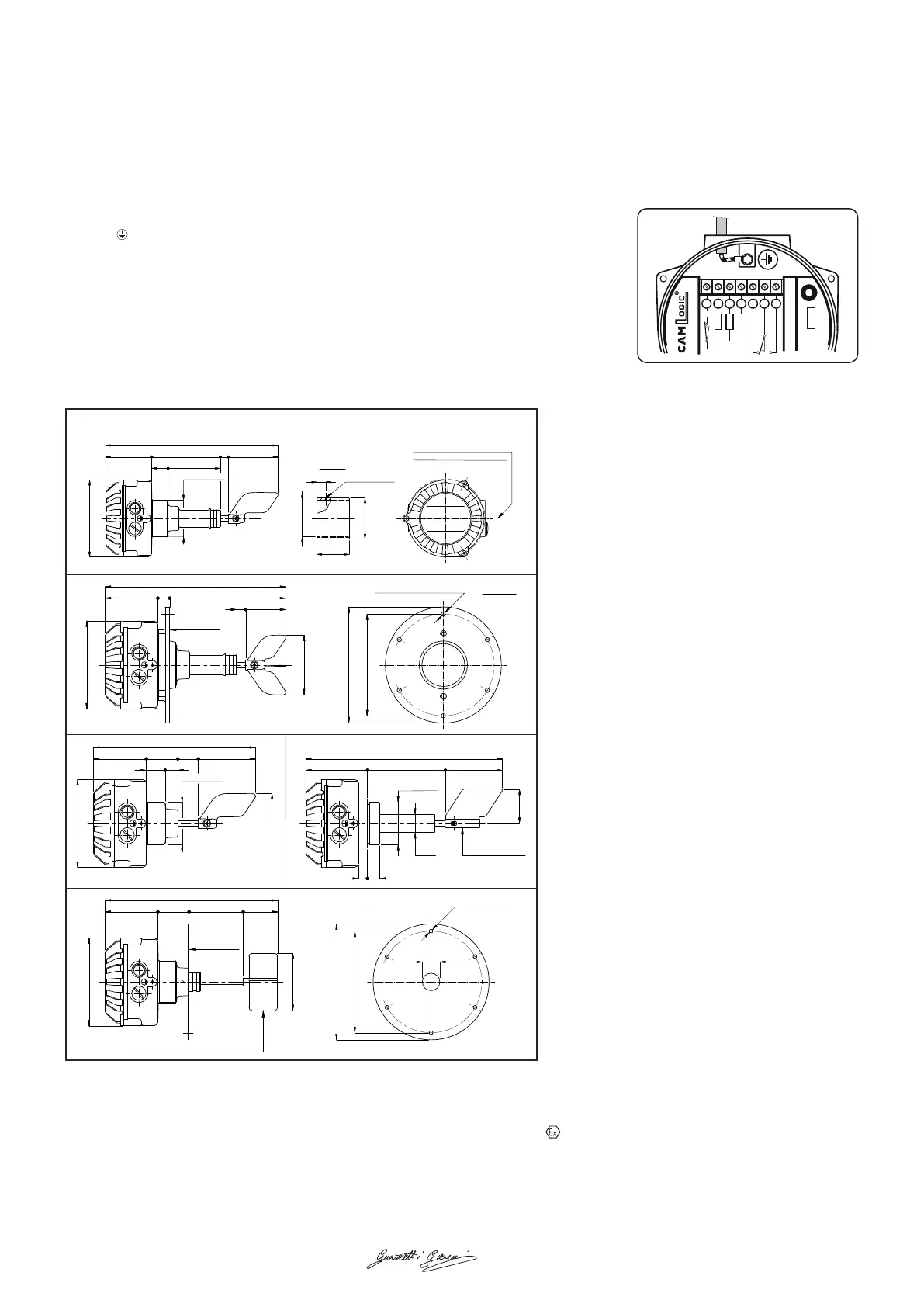
REFERENCE FIGURES
PFG-86
SLEEVE
Double ø1/2" Gas horizontal
cable inlet on the right side
Screw ø5 MA
346,5
92,5
138
16
100
10533
ø154
18
ø2" 1/2 Gas
ø82,5
65
ø2" 1/2 Gas
FLANGE
283,5
92,5
55 36 100
33 22
100
ø154
ø2" 1/2 Gas
15,5
22
Model AC4 screw
60
100
136,5
108
344,5
ø32
ø2" 1/2 Gas
PFG-86/F
PFG-86/C PFG-86/X
PFG-86/X/F
FLANGE
ø100
302
92,5 54,5
95 60
4 vanes model AC3 screw in stainless steel
ø154
6 equidistant ø7 mm holes
ø203
ø178
ø33
2 mm thick
316,5
92,5
21
203
16 70
120
6 equidistant ø7 mm holes
ø203
ø178
ø154
8 mm thick
Notified corporate body that releases the examination and entrusted of the periodic overseeing TÜV ITALIA.
Certificate number TÜV IT 13 ATEX 070 Rev.1.
The permitted ambient temperature range is -20 to +70 °C. Marking: II 1/2 D Ex ta/tb IIIC T85°C Da/Db
Firma: Giovanni Guazzetti (AD) - Data di produzione: 10/2019
 Loading...