COSTRUZIONI MECCANICHE ELETTRICHE
Use and maintenance manual for rotary level indicator series PFG05 & PFG57
PRODUCT IDENTIFICATION
The PFG05 and PFG57 series instruments are rotary level indicators for granular solids. The identification of the device is
accomplished by the specific label outside the casing, whose characteristics are shown below:
Tampering with the label entails the loss of validity of the product certifications.
Ex MARKING DETAILS
II 1/2 D ta/tb
ta/tb
Ex
Ex
IIIC
IIIC
T**
T**
IP65 ATEX MARKING (2014/34/EU / S.I. 2016 No. 1107)
IECEx MARKING (International standards)
European community marking for equipment intended for use in areas
under risk of explosion.
Group II equipment intended for use in surface industry.
Category 1 equipment, suitable for use in areas classified Zone 20 inside the
silos (only the mechanical part below the connection to process); Category 2
Zone 21 outside the silos (all parts).
Combustible dusts; combustible substance present in the area of installation
and the internal volume.
Ex symbol.
Protection method Ex t - protection from the ignition of combustible dusts
from enclosure (internal ta / external tb).
For combustible dusts type IIIC (suitable for use with any kind of dust).
Temperature class (maximum surface temperature the device can reach):
T85°C = standard version
T200°C = high temperature versions (PFG-*.../AT)
IP65 (Ingress Protection) - 6 = dust tight, no ingress of dust; 5 = protection
against jets of water, limited ingress protection.
INSTALLATION
Use and maintenance manual for rotary level indicator series PFG05 & PFG57 Page 1 of 4
IMG.1
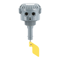
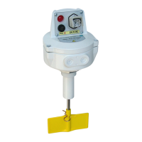
The device can be installed in any position. In case of an horizontal or titled
installation, mount the device with the cable entrance on the right side for PFG05
models, or lower side for PFG57 models. The coupling of the instrument with the wall
of the container (silos) can be either threaded or anged; images 2 and 3 show the
standard couplings. Always refer to the technical drawings supplied by the
Manufacturer together with this manual.
Protect the device from falling material or excessive weight, using protective
deectors. For cable entries, 1 (one) or 2 (two) G 1/2 threaded holes (BSPP) are
available. Seal the cable entries with cable glands or sealing caps suitable for the
operating range shown on the label. The protective caps supplied with the device are
only for protection during transport and storage, they are not suitable for the use of
the instrument and it is responsibility of the installer to replace them.
1. Production year of the instrument
2. Manufacturer data
3. Product model and electrical rating
4. Warnings
5. Ambient temperature range:
-20°C ÷ +70°C (standard application, all models)
-40°C ÷ +70°C (low temperature applications, models PFG*.../B)
Maximum process temperature:
+70°C (standard applications)
+200°C (high temperature applications, models PFG*.../AT)
6. Conformities and Notied Body number
7. Serial number
8. Ex / IECEx markings and certicate numbers
1
2
3
4
5
6
7
8
Da/Db
Da/Db
EPL (Equipment Protection Level) - Da = very high for the part operating in
Zone 20 / Db = high for the part operating in Zone 21.
0601_001_0_rev2 - 10.2022
R
S.a.s. di Guazzetti Giovanni & C.
Via dell'Industria 12 - 12/A - 42025 CAVRIAGO - RE - Italy
CF/PI/Iscr.Reg.Imprese RE 00303000350
VAT IT00303000350 REA 90637
Telefono/Phone +390522942641 / +390522941172
www.camlogic.it - email: camlogic@camlogic.it
0948