ELECTRICAL CONNECTION
The entire connection of the device must take place
while the device is de-energized. The earthing
connection (by means of an M5x8 screw and a
notched stainless-steel washer) must take place
before any other connection is established.
On the device there are two terminals for the
protective earth connection, marked by the relative
symbols (IEC 60417 / BS EN 60417-1): one inside the casing and one outside, in proximity of the cable entry. The cross-sectional
2
area of the protective earth (PE) conductor must be the same as that of the phase conductor (S), with a maximum of 16mm .
Connect both earthing terminals to the equipotential line.
Before putting the device into service, make sure that the power supply voltage corresponds to the voltage indicated on the plate.
Protect the power and signal carrying cables with an overload protection element (rated current ≤ 10A).
A disconnect switch must be present near the device, to cut off power supply in the event of a fault. Utilize cables suitable for use
up to 90°C. The wiring diagram is located inside the lid.
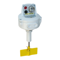
PFG57
IMG.2
4x ø7
ø140
ø120
G 1" 1/2
(BSPP)
23
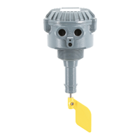
PFG05
IMG.3
ø203
ø178
6x ø7,5
G 2" 1/2
(BSPP)
35
Use and maintenance manual for rotary level indicator series PFG05 & PFG57 Page 2 of 4
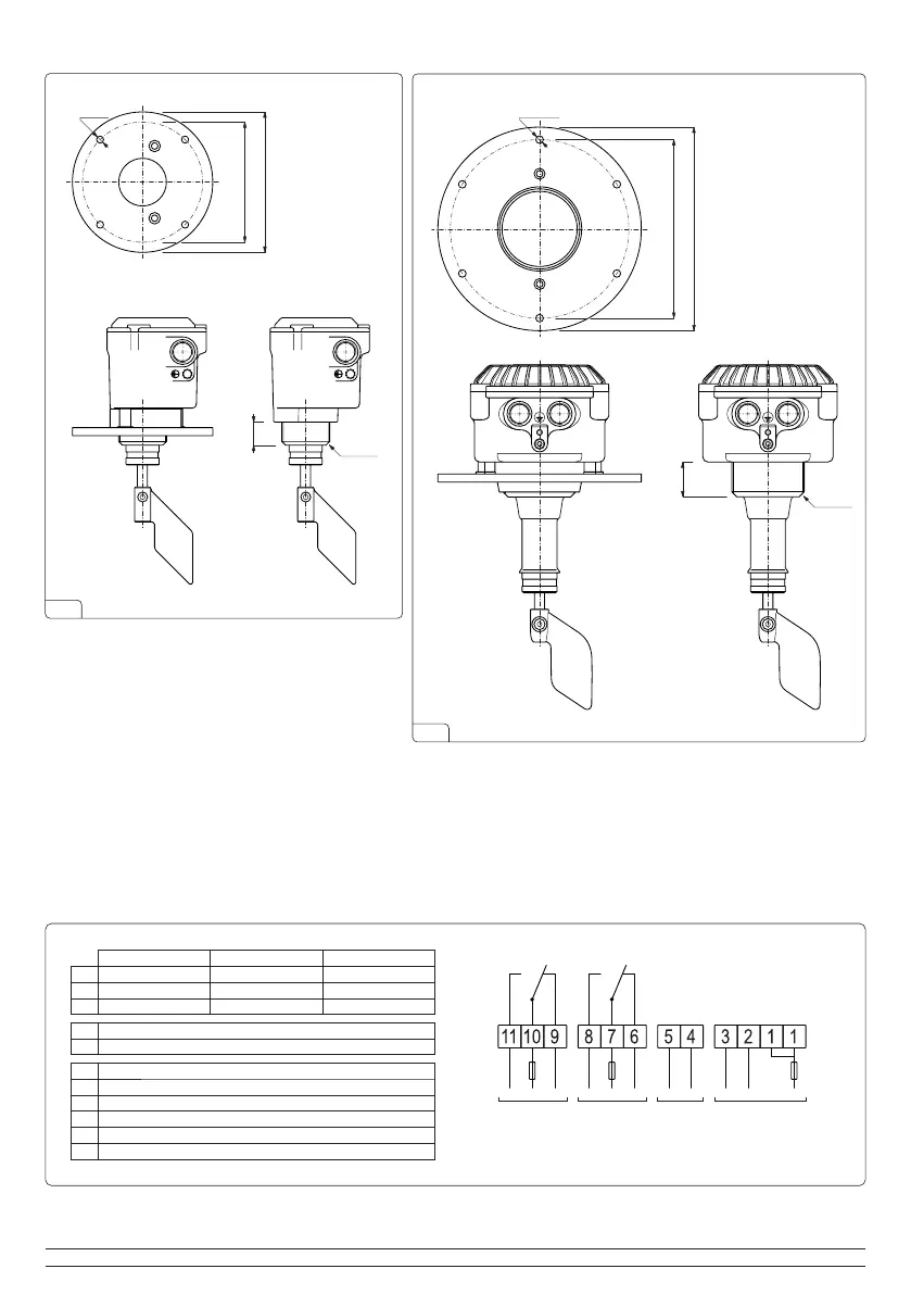
PFG05
115/230 AC 24/48 AC
24 DC
Neutral
115V (50/60Hz)
230V (50/60Hz)
1
2
3
Neutral
24V (50/60Hz)
48V (50/60Hz)
±24V
±24V
unused
Rotation control (voltage equal to contact 1)
Voltage control (voltage equal to contact 7)
4
5
Normally closed
Common (max. 10A/250V)
Normally open
Normally closed
Common (max. 10A/250V)
Normally open
6
7
8
9
10
11
ADDITIONAL
SIGNAL
(optional)
MAIN
SIGNAL
ALARMS
(optional)
POWER
SUPPLY
The diameter of the power supply cable must correspond to the tightening range indicated by the cable gland used.
0601_001_0_rev2 - 10.2022
 Loading...