24
USE
'XULQJ XVH LW LV HVVHQWLDO WKDW WKH GHYLFH DOZD\V UHPDLQV XQGHU WKH XVHUoV FRQWURO :H UHFRPPHQG ZHDULQJ
gloves. Use adequate rescue equipment and provide adequate training for the work crew so that they can
TXLFNO\ UHVFXH WKH LQMXUHG SHUVRQ WR PLQLPLVH WKH VXVSHQVLRQ WUDXPD HƪHFWV
2SHUDWLQJ3ULQFLSOHV
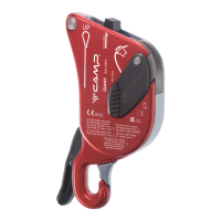
:KHQ D ORDG LV SODFHG RQ WKH DQFKRULQJFOLPEHU VLGH RI WKH URSH [11], the Druid/Druid Pro rotates on the attachment
hole [3] and the movable cam [6] URWDWHV WRZDUGV WKH Ƭ[HG FDP [5] and presses the rope in between in order to
lock the rope. The hand of the user must hold the braking side of the rope at all times [10] in order to activate the
movement of the movable cam [6] and therefore stop the sliding of the rope. For correct operation, it is essential
for the Druid/Druid Pro and the movable cam [6] to be able to move freely (ƬJ).
WARNING: Any obstacles that could block or restrict the movement of Druid/Druid Pro or of the movable cam
>@FDQSUHYHQWWKHEUDNLQJDFWLRQRIWKHGHYLFHGRQRWKROGWKH'UXLG'UXLG3URLQ\RXUKDQGVDQGGRQRW
KROGWKHWULJJHURSHQ>D@'$1*(52)'($7+ (ƬJ).
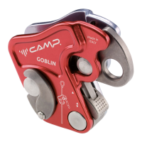
%\ SXOOLQJ WKH DFWXDWLQJ OHYHU [4], you can gradually release the movable cam in order to unlock the rope and
by controlling the braking side of the rope [10] by hand, this allows for descent. Only for Druid, in the event of
excessive action on the lever, the anti-panic locking system disengages the lever and reengages the movable cam in
order to lock the rope: the braking action of the device is conditional on keeping the braking side of the rope [10]
in hand. (ƬJD). Pulling the Druid Pro activation lever [4] rappelling is continuous and there is no anti-panic locking
device, therefore Druid Pro is suited for expert users or in rappelling situations on reduced gradients where the
anti-panic locking device is a nuisance (ƬJE). Releasing the activation lever [4] halts descent. For safety locking
VHHƬJ
:$51,1* GHWHUPLQH ZKLFK GHYLFH YHUVLRQ \RX DUH XVLQJ EHIRUH HDFK XVH 7KH SUHVHQFH RU ODFN RI DQ DQWLSDQLF
locking device is marked on the activation lever [4].
Installation of the rope, operational test
The rope must be installed in the device in the direction indicated on the markings and in ƬJ, always carry out
D WHVW RSHUDWLRQ E\ SXOOLQJ ƬUPO\ RQ WKH DQFKRULQJFOLPEHU VLGH RI WKH URSH [11] while holding the braking side of
the rope by hand [10]: the device must stop the sliding of the rope during this test (ƬJ). For installation of a drop
proof cord see ƬJ (only for expert users).
DANGER OF DEATH in the event of incorrect assembly.
Use of the EN 12841C work rope as a belay device
Use as descenders of working line must always be combined with a safety line with an EN 12841/A fall arrest device.
0D[LPXP XVH ORDG LV .J )RU WKH GHVFHQW FRQƬJXUDWLRQ VHH ƬJD. For rope climbing see ƬJE. In the event of
horizontal movements, movements on slightly inclined surfaces or with low loads you can slide the device along the
rope using the trigger [6a] as shown in ƬJ. Never release the braking side of the rope [10] during descent (ƬJF):
it can only be released in the event that the descent is halted, taking particular care and/or providing a safety loop
(ƬJ). During descent always take care that the fall arrest device does not lock up on the safety rope.
Use as EN 341/2A rescue belay device
Use of the device in compliance with EN 341/2A in combination with the appropriate rope is intended for rescue
and protection against falling from above in a rescue system. This use is not intended for work at heights. For use
WR HYDFXDWH WKH XVHU GHYLFH VHFXUHG RQ WKH KDUQHVV WKH GHYLFH VOLGHV RQ WKH Ƭ[HG URSH ƬJD. For evacuation of
 Loading...