247 CONDUCTIVITY AND TEMPERATURE PROBES
3
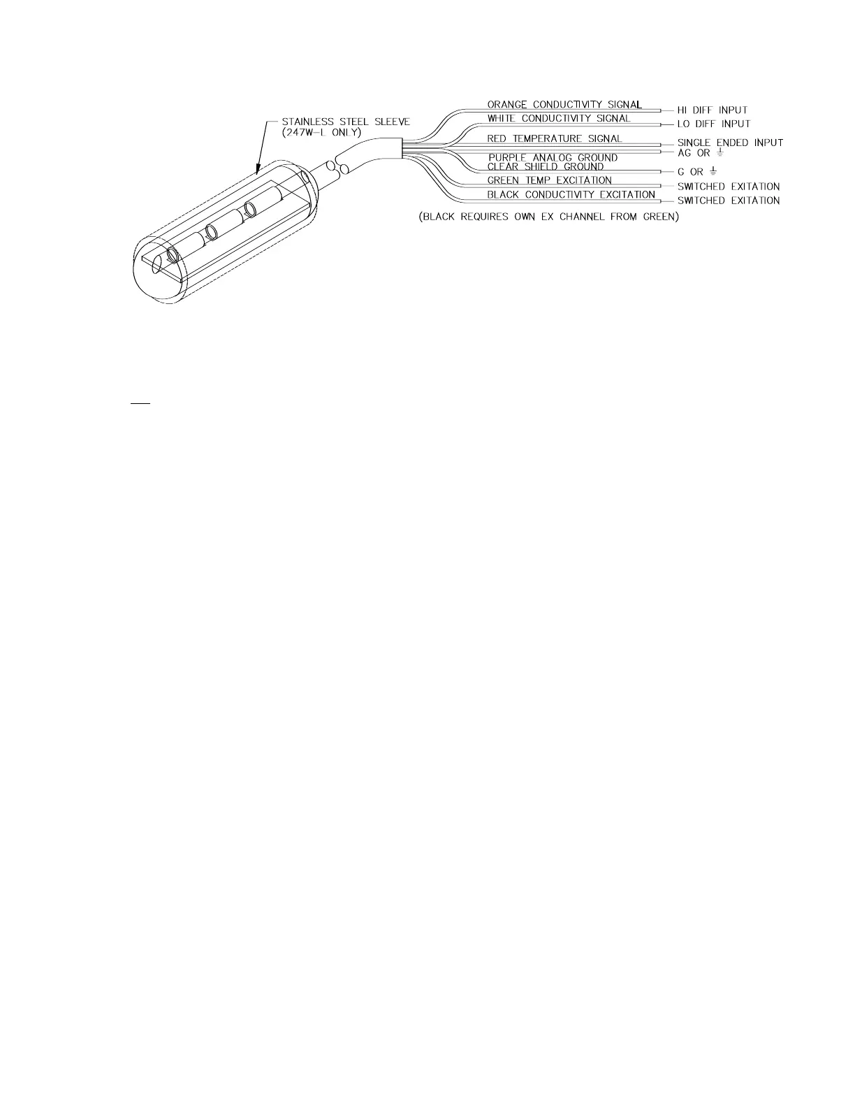
FIGURE 4-1. 247 Wiring Diagram
5.2 MEASUREMENT PROGRAMMING.
EC Results from Instructions 5 or 6 (chosen
automatically as part of the autoranging feature
of the following program segment) are
processed with Instruction 59 to produce the
resistance across the electrodes:
Make a preliminary measurement of resistance
for autoranging.
01: P6 Full Bridge
01: 1 Rep
02: 15 2500 mV fast Range
(Use 5000 mV fast for 21X)
03: 1 IN Chan
04: 1 Excite all reps w/EXchan 1
05: 2500 mV Excitation
(5000 mV for 21X)
06: 1 Loc [:Rs ]
07: -.001 Mult
08: 1 Offset
02: P59 BR Transform Rf[X/(1-X)]
01: 1 Rep
02: 1 Loc [:Rs ]
03: 1 Multiplier (Rf)
Test the preliminary measurement against each
case and make a refined measurement.
03: P93 Case
01: 1 Case Loc Rs
04: P 83 If Case Location < F
01: 1.8 F
02: 30 Then Do
05: P5 AC Half Bridge
01: 1 Rep
02: 15 2500 mV fast Range
(Use 5000 mV fast for 21X)
03: 2 IN Chan
04: 1 Excite all reps w/EXchan 1
05: 2500 mV Excitation
(Use 5000 mV for 21X)
06: 1 Loc [:Rs ]
07: 1 Mult
08: 0 Offset
06: P95 End
07: P83 If Case Location < F
01: 9.25 F
02: 30 Then Do
08: P6 Full Bridge
01: 1 Rep
02: 15 2500 mV fast Range
(Use 5000 mV fast for 21X)
03: 1 IN Chan
04: 1 Excite all reps w/EXchan 1
05: 2500 mV Excitation
(5000 mV for 21X)
06: 1 Loc [:Rs ]
07: -.001 Mult
08: 1 Offset
09: P95 End
10: P83 If Case Location < F
01: 280 F
02: 30 Then Do