Section 06 DRIVE SYSTEM
Subsection 02 (REAR DRIVE)
GENERAL
During assembly/installation, use torque values
and service products as in the exploded views.
Clean threads before applying a threadlocker. Re-
fer to
SELF-LOCKING FASTENERS
and
LOCTITE
APPLICATIONat
the beginning of this manual for
complete procedure.
A
WARNING
Torque wrench tightening specifications
must strictly be adhered to.
Locking devices when removed (e.g.: locking
tabs, elastic stop nuts, cotter pins, etc.) must
be replaced.
Hoses, cables or locking ties removed during a
procedure must be reinstalled as per factory stan-
dards
PROCEDURES
WHEEL HUB
Wheel Hub Removal
Lift and support vehicle. Refer to
INTRODUC-
TION
section for proper procedure.
Remove the wheel.
Remove the following parts:
—
Cotter pin
—
Wheel hub nut
—
Belleville washer.
1.
Cotter pin
2.
Wheel hub nut
3.
Belleville washer
NOTE: On RH side, remove also the brake caliper.
Remove wheel hub.
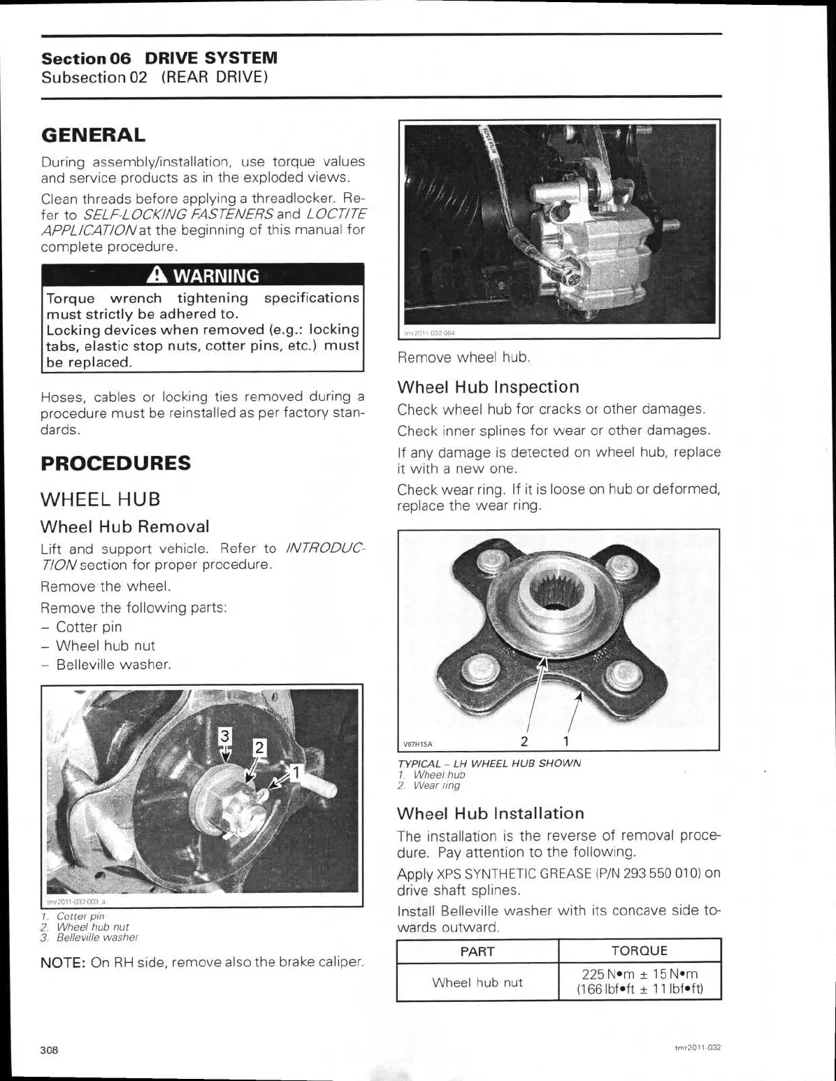
Wheel Hub Inspection
Check wheel hub for cracks or other damages.
Check inner splines for wear or other damages.
If any damage is detected on wheel hub, replace
it with a new one.
Check wear ring. If it is loose on hub or deformed,
replace the wear ring.
TYPICAL - LH WHEEL HUB SHOWN
1.
Wheel hub
2.
Wear ring
Wheel Hub Installation
The installation is the reverse of removal proce-
dure. Pay attention to the following.
Apply XPS SYNTHETIC GREASE (P/N 293 550 010) on
drive shaft splines.
Install Belleville washer with its concave side to-
wards outward.
PART
TORQUE
Wheel hub nut
225 Nom ± 15 N•rn
(166 lbf•ft ± 11 lbf•ft)
308
tmr2011-032
 Loading...