2
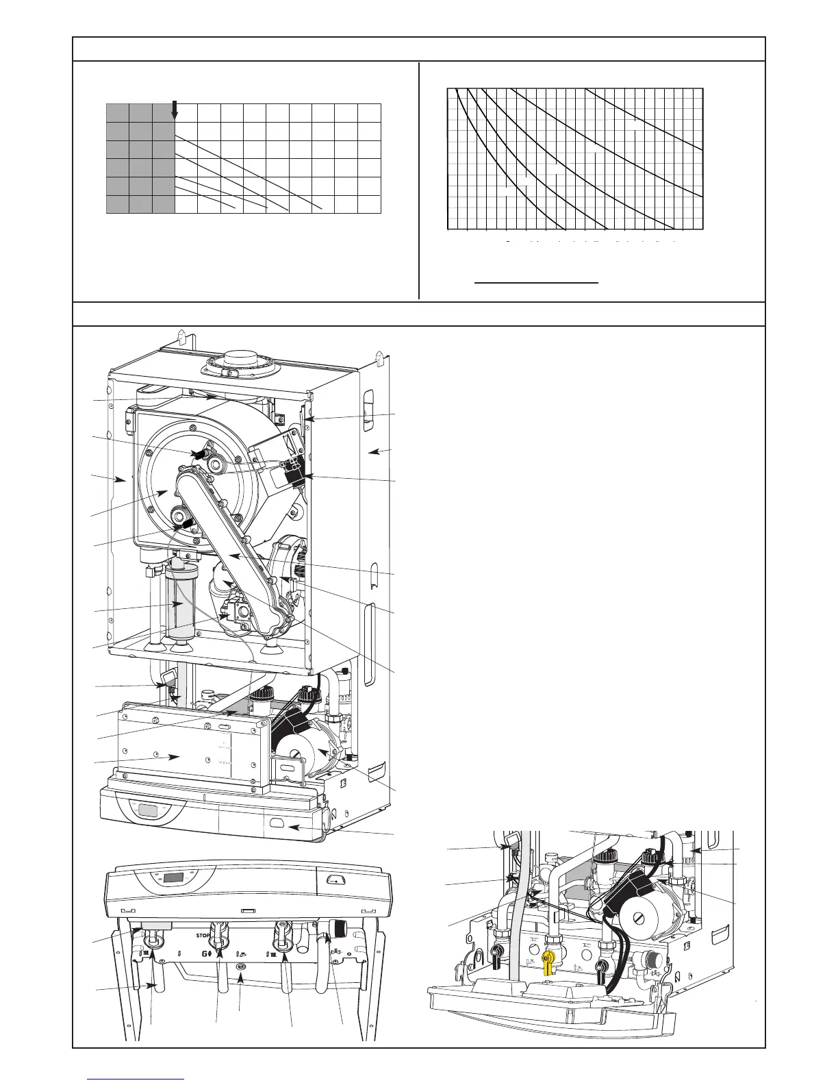
Pump and Expansion Vessel Characteristics
Components Location
N
ote : The system initial pressure should be over the following value :
System static height (in metre) + 0.7 = Initial pressure (in bar)
1
0
G
V F= high speed by-pass closed
GVO = high speed by-pass open
PV F= low speed by-pass closed
PVO = low speed by-pass open
20 40 60 80 100 120
P
f
140 160 180 200 220 240
0,7
0,8
0
,9
1,0
1
,1
1
,2
1
,3
1
,4
1,5
1,6
1,7
1
,8
1,9
2,0
Capacité maximale de l'installation (en litres)
80°C
70°C
60°C
50°C
40°C
260
P
ression à froid pour le circuit chauffage (en bar)
C
liter
System capacity chart
Central heating initial pressure when cold (in bar)
0
4
3
2
1
5
6
100
200
800
700
600
500
400
300
900
1000
1100 l/h
mCE
Débit mini (robinets thermostatiques fermés)
Hauteur manométrique
GVF
GV
O
PVF
PVO
P
ump head available
Minimum flow rate (with all heating thermostatic valves closed)
1
2
3
4
5
6
8
11
12
13
14
17
7
15
10
9
16
1.- Steel chassis complete with expansion vessel (not visible)
2.- Sealed chamber
3.- Burner and heat exchanger assembly
4.- Air / gas connection
5.- 24 V modulating fan
6.- Gas valve
7.- Ignition electrode
8.- Ionisation probe
9.- Ignitor
10.- Combustion products manifold
11.- 24 V transformer
12.- Siphon
13.- Electrical box
14.- Pump
15.- Shunt plate
16.- Pressure gauge
17.- Silencer
18.- Automatic air separator and automatic vent
19 -
Central heating flowswitch
21.- Central heating control thermistor
23.- Overheat sensor
37.- Central heating flow isolating valve
39.- Gas service tap
41.- Central heating return isolating valve
43.- Central heating pressure relief valve
46.- User’s guide
47.- Connecting tails (x3)
48.- Condensate drain
49.- Adjustable by-pass
50.- Right hydraulic assy
51.- Left hydraulic assy
23
21
19
18
23
39
4137
43
46
47
48
49
50
51