10
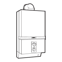
33..66 GGaass CCoonnnneeccttiioonn
- Fit the gas service cock provided using the fine fil-
ter/washer to seal the connection. Fit the nut and
o
live onto the 15 mm gas supply pipe and tigh-
ten, (see fig. 9).
-
Test the complete gas installation for soundness
and purge.
33..77 WWaatteerr CCoonnnneeccttiioonnss
- Remove the plastic covers protecting the water
inlet and the water outlet connections.
- Fit the water service cock provided to the right hand
connection at the bottom of the appliance using the
coarse filter/washer to seal the connection, (see fig.
10).
- Fit the nuts and olives onto the supply and delivery
pipes.
- Connect the inlet supply to the water service cock and
tighten.
- The water service cock supplied with the appliance
incorporates a drain plug.
- Ensure that all water connections are fully tightened.
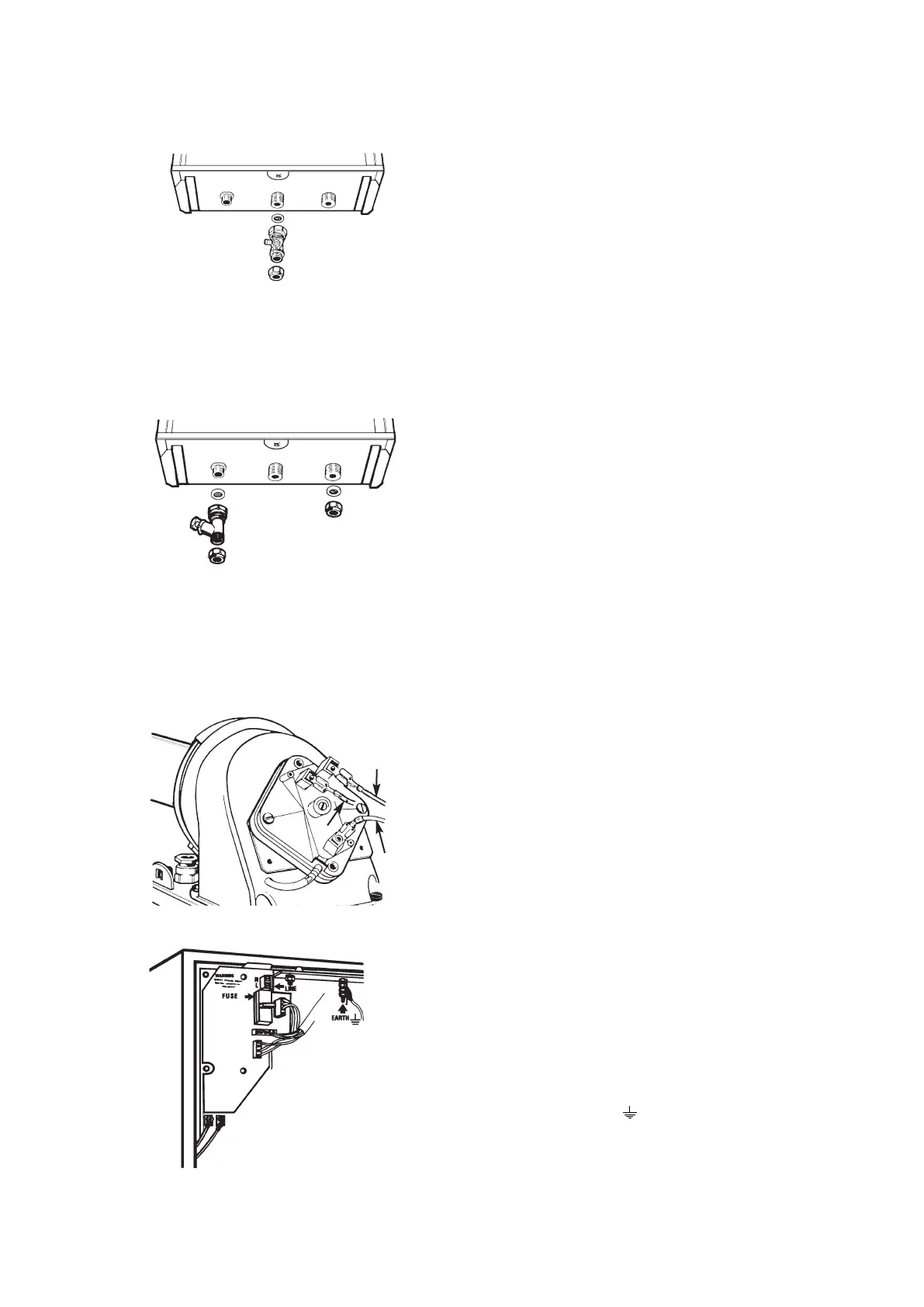
33..88 EElleeccttrriiccaall ccoonnnneeccttiioonnss
33..88..11 PPrreessssuurree SSwwiittcchh
- Connect the wires at the top of the appliance to
the pressure switch, (see fig. 11).
- The
ggrreeyy
wire is connected to nor
mally closed (NC
1) contact.
- The
ppiinnkk
wire to the normally open (NO 2)
contact.
- The
vviioolleett
wire to the common (P) contact.
- Fit the flue turret cover passing the wire through
one fo the slots provided and secure with the
screws provided.
- See figure.
33..88..22 MMaaiinnss CCoonnnneeccttiioonn
- Pass 0.75 mm
2
heat resisting cable through cable
gland.
- The ear
th wire (open yellow) must be connected
to the earth pillar ( ) (see fig. 12).
- The live (brown) and neutral (blue) should be
connected as indicated into the terminal block.
- Check that component plugs are pushed home.
- Check for continuity
, polarity and ear
thing.
FFiigg.. 99
FFiigg.. 1100
FFiigg.. 1111
FFiigg.. 1122
G
V
P
 Loading...