5
22..66 FFlluuee TTeerrmmiinnaall AAsssseemmbbllyy
The flue may be fitted from inside or outside of the
b
uilding. If fitting from inside the flue duct should be
assembled into the air intlet duct and the assembly
p
assed trough the hole in the wall. The outside dia-
meter of the terminal is the same as outside diame-
t
er of the air inlet duct.
22.. 77 AAiirr ssuuppppllyy
The appliance does not require any purpose provi-
ded ventilation.
22..88 EElleeccttrriiccaall CCoonnnneeccttiioonnss
The appliances must be earthed.
The installation should be undertaken by a compe-
tent electrician and should be in accordance with the
current edition of B.S 7671.
Par
ticular attention should be paid to cross bonding.
The appliance must be provided with a means of
isolation. If installed in a bathroom the means of iso-
lation must be external to the bathroom or a double
pole cord switch fitted.
Acceptable methods of connection are :
1. A switched, double pole fused spur with 3 mm
contact separation on all poles.
2. A double pole switch where the supply must be
suitably fused 3 A.
3. An un-switched socket outlet compling with
BS 1363.
The method of connecting the plug brown wire to
live (L) blue wire to neutral (N) and green/yellow
to earth ( ), see fig. 3.
A three core cable should be used and a heat resis-
ting cable of 0.75 mm
2
(24 x 0,2 mm) is considered
suitable.
T
he cable should be passed through the gland on
the top of appliance and the clamp tightened to
secure the cable. Ensure current carrying conductors
b
ecome taught before earthing conductor should
cable slip from the cord anchorage. Connection to
the appliance should be made in accordance with
d
iagram (see section 3, 8, 2).
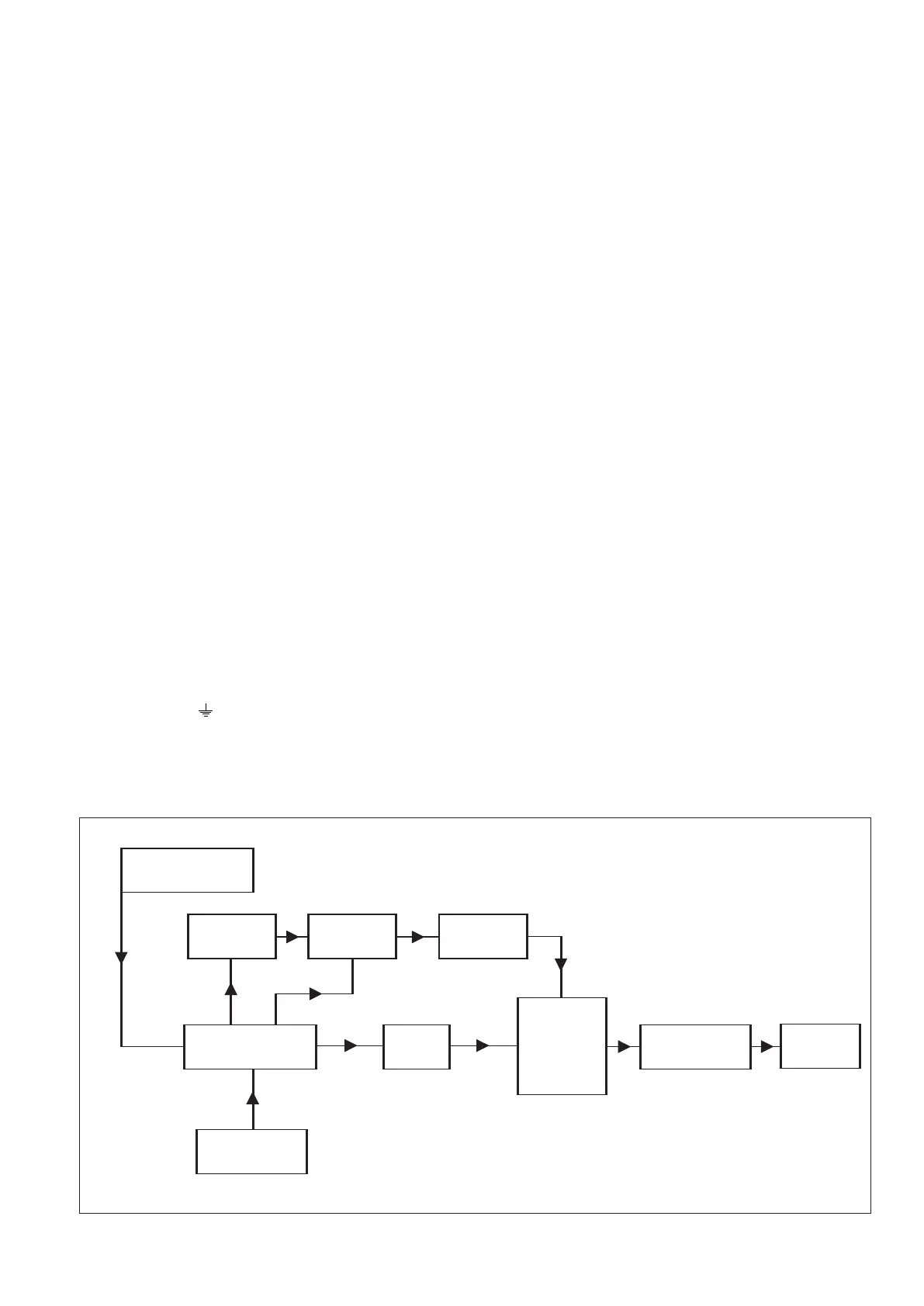
22..99 DDeessccrriippttiioonn ooff OOppeerraattiioonn
R
ead in conjunction with figs 1, 2 and 4).
The controls on the Britony FlexiFlue comprise of a
range of thermal, electric and electronic switches.
Broadly, the thermal controls are for the pilot flame
supervision, the electrical controls are functional
switching and the electronic controls act as a securi-
ty for the functional controls.
The cir
cuit is designed so that, under normal condi-
tions, the fan runs continuously at low speed and
automatically changes to high speed when the gas
valve opens. If, however, the incoming air tempera-
ture approaches 0°C the integral frost protection
thermostat interrupts the low fan speed signal.
Under this condition, if ther
e is a demand for hot
water, then the fan recommences at high speed.
There is an in-built delay circuit to prevent the safe-
ty devices operating prematurely.
The pilot can only be established under the control
of the thermocouple flame failure circuit after the
mains electricity connection is made since it is
dependent upon the energising of relay-RL1.
If the air flow is not proved on high speed the flame
supervision device will operate by interrupting the ther-
mocouple as a result of the de-energising relay-RL1.
ELECTRIC SUPPLY
FROST
THERMOSTAT
FAN
PRESSURE
SWITCH
MICRO SWITCH
RELAY
RL2
RELAY
RL1
GAS VALVE
THERMOCOUPLE
THERMO
ELECTRIC
VALVE
FFUUNNCCTTIIOONNAALL FFLLOOWW DDIIAAGGRRAAMM
 Loading...