Do you have a question about the Canoga Perkins EDGEACEESS 9145E and is the answer not in the manual?
Information about installing the 9145E in telecommunication facilities where the National Electric Code applies.
Details on the design and testing of cabling for the 9145E, meeting GR-1089 and GR-63 standards.
Warnings and guidelines for connecting AC and DC power supplies, including disconnect device recommendations.
Information about the internal fuses for AC models (2A) and DC models (3A Slo Blo).
Guidance on using external Surge Protective Devices (SPD) for AC powered 9145E units.
Procedures for grounding the 9145E chassis and electrical connections, including wire gauge recommendations.
Information on protecting the 9145E from lightning surges using shielded intra-building cabling.
Precautions for handling static-sensitive components, such as SFP optical modules, using static mitigation procedures.
Details on the operating temperature ranges for standard (0°C to 50°C) and hardened (-40°C to +65°C) models.
Information about the airflow scheme and fan replacement policy, noting fan replacement is not field-serviceable.
Compliance with FCC rules and Canadian regulations for emissions and immunity criteria.
Notes that no special accessories are needed for emission and immunity compliance.
Warning about potential hazards with fuses in the neutral path during servicing.
Information on product disposal and recycling according to local standards.
Overview of the 9145E as a second-generation Network Interface Device for Metro Ethernet Forum compliant services.
Details on physical, environmental, power requirements, and regulatory compliance for the standard 9145E.
Specifications for the hardened version including extended temperature range, physical, environmental, and power requirements.
Describes options like rack mounting (19"/23") and wall mounting for the 9145E.
Details on mounting the 9145E in 19" or 23" racks using specific kits, including dual unit configurations.
Instructions for mounting the 9145E on a wall using keyhole cutouts and a provided template.
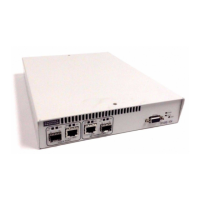
Describes the 9145E's design with front/rear ports and availability as normal/hardened, standard/enhanced NID.
Details the hardware options and port configurations available for the 9145E, including front and rear panel layouts.
Describes the ports and connectors found on the front panel of the 9145E, including User, Network, and Multipurpose ports.
Details the different power options available for the 9145E rear panel, including AC, DC, and AC/DC configurations.
Provides information on UTP and SFP connectors for service data transmission, supporting 10/100/1000BASE-T.
Details the console and Ethernet management ports for device control and configuration.
Explains the DE-9 female connector for serial console port communication with VT100 terminals or emulators.
Describes the RJ45 port for remote management using Telnet, SSH, and SNMP V1/V2C/V3.
Outlines the default active connector settings for User, Network, and Multipurpose ports.
Explains the different power connector types for the 9145E, including IEC 320 AC and DC terminal blocks.
Lists the AC (100-240 VAC) and DC (36-72 VDC, 18-36 VDC) voltage and current requirements for the 9145E.
Details the single AC power connector (IEC 320) on the rear panel of the 9145E.
Describes the dual AC power connectors for redundant power supply configurations on the 9145E.
Explains the single DC power terminal receptacle on the rear panel of the 9145E.
Details the redundant DC power terminal receptacles on the rear panel of the 9145E.
Describes the mixed AC and DC power interface on the rear panel of the 9145E.
Explains the function of front panel LEDs for system and port status indication.
Details indications for STATUS, POWER, SPD, and LNK/ACT LEDs in the management section.
Explains SPD and LNK/ACT LED indications for User, Network, and Multipurpose ports.
Provides instructions for unpacking, installing, and setting up the 9145E, including console connection.
Steps for safely unpacking the 9145E and its accessories from the shipping container.
Describes the different ways the 9145E can be mounted: rack, wall, or flat surface.
Details on mounting the 9145E in 19" or 23" racks using specific kits, including dual unit configurations.
Instructions for mounting the 9145E on a wall using keyhole cutouts and a provided template.
Guidelines for placing the 9145E on a secure flat surface like a shelf or desk, ensuring ventilation.
Steps for determining and installing compatible SFP modules into the 9145E ports.
Instructions for connecting both AC and DC power to the 9145E, including safety precautions.
Details on connecting the 9145E to a standard AC power outlet using the provided IEC 320 power cord.
Detailed procedure for connecting DC power to the 9145E, including wire gauge and polarity checks.
Information on internal fuses and recommended minimum external fuse ratings for DC power.
Steps for connecting the grounding lug kit to the 9145E chassis for safety, including torque specifications.
Instructions for connecting fiber optic and UTP Ethernet cables to the 9145E.
Procedure for connecting optical fiber cables to SFP modules, ensuring proper orientation and lock.
Steps for connecting UTP cables to RJ45 connectors, ensuring the locking tab is properly seated.
Explains how LEDs on the front panel indicate system and port status during power-up.
Describes the function of the PWR and STA LEDs indicating device condition and state.
Explains the Link/Activity and Speed LEDs for the Ethernet management port.
Details the indications of SPD and LNK/ACT LEDs for User, Network, and Multipurpose ports.
Methods for managing the 9145E via console, Ethernet, or network ports.
Guide to setting up HyperTerminal for console access to the 9145E, including port settings.
Addresses issues related to significant signal loss in optical links and cable inspection.
Identifies fault conditions indicated by front panel LEDs and the System Alarms Log.
Explains the Remote Fault signal and its indication on SPD and ACT/LNK LEDs.
Describes how Link Loss Forwarding propagates faults and stops signal transmission.
Procedures for verifying link connectivity and quality using PING and Latency/Jitter tests.
Instructions for verifying network connectivity by sending PING requests.
Details on measuring link performance and quality using latency and jitter tests.
Methods for diagnosing faults on optical links using two loopback modes.
Describes the User Mode loopback configuration for testing the local module.
Describes the Network Mode loopback configuration for testing the remote module.
Emphasizes maintaining components and cables for optimum system operation, especially fiber optics.
Steps for measuring transmitter output power and receiver input power.
Procedure for inspecting, connecting, and measuring transmitter output power.
Steps for measuring receiver input power at both local and remote sites.
Steps to calculate fiber link attenuation by subtracting receiver input power from transmitter output power.
| Ports | 4 x 10/100/1000Base-T, 2 x 100/1000Base-X SFP |
|---|---|
| Switching Capacity | 12 Gbps |
| Humidity | 5% to 95% non-condensing |
| MAC Address Table | 8K |
| Jumbo Frame Support | 9, 216 bytes |
| Power Supply | 100-240V AC, 50-60Hz, 20W max |
| Operating Temperature | -40°C to 65°C |
| Storage Temperature | -40°C to 85°C |