Do you have a question about the Canon BJ-10E and is the answer not in the manual?
Take care not to get caught in moving and rotating parts of the printer.
Warning about high-temperature components within the printer logic circuit.
Follow local laws and regulations when disposing of Ni-Cd batteries.
Instructions for unpacking and handling the BJ cartridge.
Do not touch or wipe nozzles with tissue paper to prevent clogging.
Avoid electrostatic discharge and ink leakage during handling.
Use only supplied AC adapter and handle Ni-Cd battery pack safely.
Precautions for adjustment, releasing plastic hooks, and electrostatic discharge.
Adjust head gap using dials; use a felt-tip pen to mark positions.
Avoid electrostatic discharge when handling electronic components.
Protective functions for BJ cartridge (copying, maintenance jet, cleaning).
Protective functions for Ni-Cd battery pack (auto power-off, auto charge-off).
Printer has self-diagnostic function to analyze hardware failures.
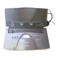
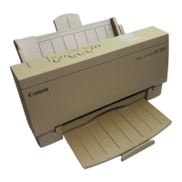
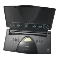
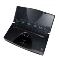
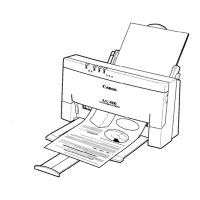
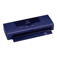
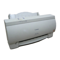
Unpacking and checking printer parts.
Functions related to printer service operations.
Explains printer errors indicated by lamps and beeper.
Service functions controllable via control keys and power switch.
How to clean the BJ cartridge nozzle surfaces using control keys.
Details the internal components and their functions.
Detailed structure of the bubble jet head unit.
Description of bubble jet nozzles.
Components of the control section.
Details about the MPU.
Details the components of the power supply section.
Describes input power sources (AC adapter, Ni-Cd battery).
Procedures for disassembling and reassembling the printer.
Procedures for adjusting printer settings.
Location of adjustment points for head gap.
Steps to prepare for head gap adjustment.
Detailed steps for head gap adjustment.
Guide for diagnosing and resolving printer issues.
Explains error states indicated by lamps and beeper.
Table of error states and their indications.
Recovery procedures for indicated errors.
Recovery steps for RAM errors.
Recovery steps for home position errors.
Recovery steps for Ni-Cd battery errors.
Errors without indicator lamp signals.
Lists error conditions not shown by indicators.
Recovery methods for various error conditions.
Troubleshooting steps when there is no power.
Troubleshooting steps for printing errors.
Diagrams of the printer's electrical circuits.
Diagram showing connections between printer components.
Detailed wiring diagram of the printer circuits.
Circuit pattern drawing for the printer's boards.