Do you have a question about the Canon imageRUNNER 1019j and is the answer not in the manual?
Information about manual issuance, scope, and applicability to localities.
Manual may contain errors; updates and new editions will be released as needed.
Product names are registered trademarks; manual is copyrighted and reproduction is restricted.
Use of the manual should be supervised to avoid disclosure of confidential information.
Explains symbols used in the documentation to indicate special information.
Rules for interpreting diagrams, electrical signals, and microprocessor operations.
Technical specifications for the Automatic Document Feeder (ADF).
Technical specifications for the fax functionality of the machine.
Lists various functions and their details, including print speeds.
Lists supported paper types, sizes, and weights for the machine.
Step-by-step guide for installing the card reader accessory.
Procedures for installing PCL printer kit and importing user data.
Procedures for installing the Network Interface Adapter iN-E11.
Describes the functional construction of the machine into 7 blocks.
Explains the machine's operational sequence from power on to last rotation.
Details specifications, control methods, and major components of the exposure system.
Describes the sequence of operations when the machine is powered on.
Explains control mechanisms like enlargement/reduction and dirt sensor.
Procedure for removing and replacing the laser scanner unit.
Details the specifications and control mechanism of the image formation system.
Explains the indirect electrostatic method and blocks of the image formation process.
Procedure for removing the developing unit.
Procedures for removing registration rollers and related components.
Procedure for removing the registration sensor and its cover.
Describes the control panel's components and control by the image processor PCB.
Explains the function and operating conditions of the machine's cooling fan.
Procedures for detaching various external covers of the machine.
Overview of the ADF, its drive mechanism, and sensors.
Details machine operation modes like Forward Pickup/Delivery and Forward Feed/Reversal.
Explains the paper pickup process within the ADF.
Method for adjusting image parallelism by changing spring positions.
Procedures for inter-channel output correction after replacing CS or copyboard glass.
Lists electrical components in the main body with their functions and part numbers.
Lists sensors in the main body with their functions and part numbers.
Explains various service mode categories like #SSSW, #MENU, #NUMERIC, etc.
Illustrates how to navigate and use the service mode for Bit SW and Parameter settings.
Lists default settings for service mode menus (#SSSW, #MENU).
Details various tests (MODEM, FUNCTION, Operation Panel) within the service mode.
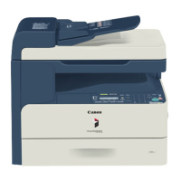
| Print Resolution | 600 x 600 dpi |
|---|---|
| Connectivity | USB 2.0 |
| Duplex Printing | Manual |
| Copy Resolution | 600 x 600 dpi |
| Type | Monochrome Laser Multifunctional |
| Print Speed | 19 ppm |
| Paper Capacity | 250 sheets |
| Paper Input (Standard) | 250 sheets |
| Paper Output | 100 sheets |
| Paper Sizes | A4, A5, B5 |
| Copy Speed | 19 cpm |
| Multiple Copy | Up to 99 copies |
| Scan Resolution | 600 x 600 dpi |
| Scan Destinations | PC |