Do you have a question about the Canon imageRUNNER 1750 Series and is the answer not in the manual?
Regulations concerning laser products enforced by the US FDA, applicable to products manufactured on or after Aug 2, 1976.
Precautions for servicing laser assembly areas, including turning off power and handling warning labels.
Precautions for servicing laser assembly areas, including turning off power and handling warning labels.
Details the function of the main power switch and control panel power switch for machine operation.
Guidelines for using the power cord and socket-outlet for safe operation.
Information on toner composition, handling, and precautions regarding fire and contact with skin or clothing.
Safety warnings regarding battery replacement and disposal due to explosion risk.
Precautions to take before servicing, including turning off power and disconnecting the plug.
Precautions for cleaning, ensuring solvent vaporization before assembly.
General precautions for disassembling and reassembling the device, including power disconnection and screw handling.
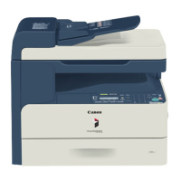
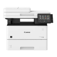
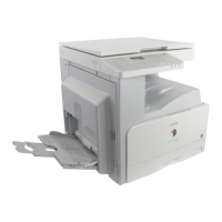
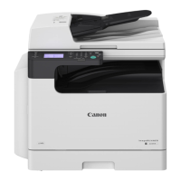
Lists the available models (imageRUNNER 1750/1740/1730) and their configurations.
Highlights key product features including low running cost, improved maintainability, performance metrics, and installability.
Details technical specifications such as paper handling, speed, power requirements, dimensions, and weight.
Provides external views and lists of components for various parts of the machine.
Describes the machine's composition of 6 major blocks: Exposure, Controller, Laser Exposure, Image Formation, Fixing, and Pickup/Delivery Systems.
Details specifications, controls, and functions of the original exposure and feed system.
Explains the configuration and functions of the main controller, including PCBs and memory modules.
Covers specifications, controls, and main configuration parts of the laser exposure system.
Details the list of image formation specifications, major components, and the image formation process.
Explains the fixing system's overview, features, specifications, and major components.
Details the specifications, parts configuration, sensors, and route of drive for the pickup feed system.
Covers controls for software counters, fans, power supply, and service tasks.
Explains Embedded RDS features, benefits, service cautions, and setup procedures.
Outlines the chapter's scope on printer disassembly/reassembly and provides safety precautions for technicians.
Provides external and internal views of the machine, listing parts and their references for disassembly.
Details various connectors used in the printer's electrical system, with their symbols, names, and PCB connections.
Details the location of external covers and internal components, with procedures for their removal.
Shows the location of components within the Original Exposure/Feed System and adjustment during parts replacement.
Details the location and procedures for removing DC Controller PCB and Main Controller PCB.
Explains the procedure for removing the Laser Scanner Unit and the necessary adjustments after replacement.
Illustrates the location of image formation system components and procedures for their removal.
Provides procedures for removing the Fixing Assembly and the Fixing Drive Unit.
Details procedures for removing various components within the pickup feed system.
Describes adjustments required in field service works when replacing parts, classified by function.
Details adjustments for CIS Unit, Copyboard Glass, and ADF Reading Glass in service mode.
Provides remedies for adjusting basic image position, including left/right edge margins and ADF squareness.
Lists initial check items related to site environment, paper, paper setting, consumable parts, and periodical servicing.
Explains how to select and view test print types for image failure analysis.
Details common image failures like toner soiling, poor transfer, and image smear, with causes and field remedies.
Describes methods for upgrading system software for the host machine, finisher, and optional cassette.
Provides an overview of error codes, classifying them into Error code, Jam code, and Alarm code.
Details specific error codes, their items, descriptions, and remedies for fixing issues.
Lists jam codes for the Main Unit and ADF, including ACC ID, Jam Code, Type, Sensor Name, and Sensor ID.
States that there are no alarm codes for the service technician in this machine.
Lists service modes available for checking/setting fax functions, parameters, and system configurations.
Provides detailed discussions of various service mode settings, including SSSW, NUMERIC, and SCAN configurations.
Explains how to check installation procedures and describes symbols used in illustrations.
Outlines the sequence for installing optional machine components like Drum Heater, Card Reader, and Fax Board.
Provides points to note and checking contents for installing the Drum Heater-D1 option.
Details checking contents and installation procedures for the Copy Card Reader-F1 and its attachment.
Explains how to check contents and remove covers for the System Upgrade RAM-C1 installation.
Lists special tools required for maintenance, including digital multimeter and test charts.
Provides basic sequences for printing operations, illustrating timing for various components.
Presents detailed circuit diagrams for various parts of the machine, showing PCB connections and component layouts.
Details user mode settings for common configurations, timer settings, adjustment/cleaning, and copy settings.