Do you have a question about the Canon imageRUNNER 7095 and is the answer not in the manual?
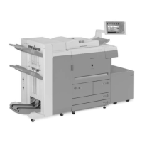
Describes the overall system construction and configurations with various accessories.
Details product specifications including parts, usage, safety, functions, and properties.
Provides safety precautions related to laser light, CDRH regulations, and toner handling.
Covers points to note before installation, site selection, and checking contents.
Details the procedure for unpacking and installing the machine and its various components.
Explains how to check network connections using PING command and remote host address.
Covers common network issues and troubleshooting steps like loop back and local host checks.
Details the procedure for installing the card reader unit.
Details the functional construction of the copier, dividing it into five functional blocks.
Outlines the basic sequence of operations, particularly for power-on.
Details the construction and functions of the main controller, including its components and interfaces.
Describes the sequence of operations when the machine starts up, including software loading.
Explains the configuration of image processing modules and the flow of image data.
Details procedures for replacing parts related to the main controller box and PCB.
Details specifications, controls, and major components of the original exposure system for iR7105/7095 and iR7086.
Outlines the basic sequence of operations for the original exposure system at power-on for both models.
Explains controls for scanner drive system, scanning lamp, and original size detection.
Details procedures for replacing components of the original exposure system like CCD unit, glass, lamp, etc.
Describes the laser exposure system, including laser light, scanner motor, and polygon mirror.
Details the basic sequence of operations for the laser exposure system, including motor and lamp control.
Explains controls for laser activation timing, intensity, scanner motor, and laser shutter.
Details the procedure for replacing the laser scanner unit.
Details the construction and major components of the image formation system.
Outlines the steps involved in the machine's image formation process.
Explains potential control for determining optimum grid bias, laser output, and developing bias.
Details the primary, pre-transfer, and dust-collecting charging mechanisms.
Describes the components and control systems associated with the developing assembly.
Details procedures for replacing parts within the image formation system, like process unit, lamps, and assemblies.
Details specifications, arrangement of rollers/sensors, and control system for the pickup/feeding system.
Outlines the basic sequence of operations for right deck and cassette pickup.
Explains jam detection outline, delay jams, and stationary jams.
Details the outline and detection mechanisms for paper presence, level, and size in cassettes.
Describes the pickup operation and paper size detection for the manual feed tray.
Details the outline, lifter limiter, and paper detection mechanisms for decks.
Covers copying on the first/second side and sequences of operations for duplex feeding.
Explains the mechanism for detecting double feeding using ultrasonic sensors.
Details procedures for replacing various parts within the pickup/feeding system.
Details the fixing system construction, drive system overview, and control mechanisms.
Outlines the basic sequence of operations for the fixing system, including heater control.
Explains control mechanisms for fixing roller temperature, transparency, heavy paper, and power save modes.
Details error detection related to fixing temperature control, including thermistors and thermal switches.
Details procedures for replacing components of the fixing system, such as the fixing unit, rollers, and heaters.
Overview of the control panel, including PCBs and LCD, with related service modes.
Shows the arrangement, names, and functions of fans for iR7086 and iR7105/7095 models.
Details the DC power supply, backup battery, and energy-saving functions.
Covers replacement procedures for various external and control components like drive assemblies, PCBs, and switches.
Overview of MEAP, including its definition, counter mechanisms, and platform construction.
Explains RDS specifications, including application operation, service center settings, communication tests, and troubleshooting.
Lists parts that require periodic replacement and their expected life based on usage.
Details parts that may need replacement due to wear or damage, including their part numbers and life.
Provides basic procedures, charts, and points to note for scheduled maintenance tasks.
Covers making pre-checks and performing checks on the printer and reader sides for image quality.
Details standards of image position and adjustments for side registration, margins, and non-image width.
Discusses component replacement and mirror base position adjustment for the scanning system.
Covers replacement of the laser scanner unit and checking the laser power.
Explains adjustments for charging wire height and fixing roller pressure.
Details adjustments for lower roller pressure, fixing heater, and electrical components.
Covers site installation, originals, copyboard, charging assemblies, developing unit, paper, and periodically replaced parts.
Lists and describes electrical components including clutches, solenoids, motors, fans, PCBs, and sensors.
Lists error codes, their descriptions, and remedial actions for various faults.
Provides detailed explanations and corrective actions for specific error codes like E000, E001, E002, etc.
Lists jam codes for the printer, DADF-Q1, and DADF-M1, along with sensor information.
Provides a table of alarm codes, locations, and descriptions.
Explains service mode screen configuration, entering/exiting modes, backing up, and initial screens.
Details FEEDER items for adjusting sensor sensitivity, belt cleaning, and motor checks.
Explains I/O display modes, including DC-CON, R-CON, FEEDER, SORTER, and MN-CONT.
Covers adjustments for AE, ADJ-XY, HV-SP, FEED-ADJ, CST-ADJ, and others.
Details function items for COPIER, FEEDER, and SORTER, including installation and operational checks.
Covers option settings for COPIER, FEEDER, SORTER, and BOARD, including paper settings and special modes.
Explains test print modes for COPIER and NETWORK, including PG settings and PING commands.
Provides an overview of upgrading work, functions, operations, and points to note for downloading.
Details installing system software from CD/SST to PC, copying to USB, and making connections.
Explains formatting the HDD for all partitions or selected partitions.
Covers downloading system software (ALL, Single, Overwriting) and version upgrades using USB.
Lists special tools required for servicing the copier, including their tool numbers, shapes, ranks, and remarks.
Lists solvents and oils used for cleaning and lubricating, including their uses, compositions, and remarks.
| Type | Digital Multifunction Printer |
|---|---|
| Functions | Print, Copy, Scan, Fax |
| Print Speed | 95 ppm |
| Warm-Up Time | 30 Seconds or Less |
| Print Resolution | 1200 x 1200 dpi |
| Paper Sizes | Letter, Legal |
| Duplexing | Automatic |
| Interface | USB 2.0, Ethernet |
| Power Consumption | 1.5 kW (max) |
| Weight | 160 kg |
| First-Copy Time | 3.9 seconds |