Do you have a question about the Canon iR5570 Series and is the answer not in the manual?
| Resolution (Scan) | 600 x 600 dpi |
|---|---|
| Functions | Print, Copy, Scan |
| Print Speed (Black) | 55 ppm |
| Maximum Original Size | 11 x 17 inches |
| Warm-Up Time | 30 Seconds |
| Duplexing | Standard |
| Memory (Standard) | 256 MB |
| Interface | USB 2.0, Ethernet |
| Power Consumption | 1.5 kW (Maximum) |
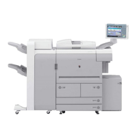
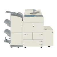
Identifies the service manual for the Canon iR6570/5570 series.
Details the overall system configuration with input/output and printing/transmission accessories.
Outlines machine specifications, parts, usage, maintenance, safety, function lists, and printing speeds.
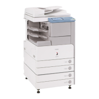
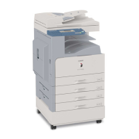
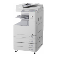
Identifies external parts of the machine with numbered labels for easy reference.
Provides instructions on basic machine operations, including turning power on and off.
Lists and describes various user-configurable settings such as common settings, timer settings, and system controls.
Explains user-level maintenance tasks like cleaning and checks to ensure proper machine operation.
Covers crucial safety information regarding laser units, CDRH regulations, and toner handling.
Details the machine's operational specifications, including paper handling, printing speed, and dimensions.
Lists various functions and supported paper types for the machine.
Outlines essential pre-installation checks for site requirements, environmental conditions, and component verification.
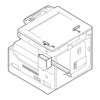
Provides step-by-step instructions for unpacking the machine and installing its components safely.
Guides on verifying network connectivity using Ping and remote host addresses.
Offers steps to diagnose and resolve network connection issues, including loopback and local host checks.
Details the procedure for installing the optional copy tray (Copy Tray-L1).
Provides installation instructions for the card reader attachment.
Outlines steps for installing the NE Controller-A1 unit.
Details the procedure for installing the original holder assembly.
Provides instructions for installing the cassette heater unit.
Describes the functional construction and wiring diagram of major PCBs.
Explains the operational sequences at power-on (30-sec, low-temperature, high-humidity) and during copying/printing.
Details the construction and mechanisms of the main controller block.
Shows the major control mechanisms of the main controller according to connectors.
Explains the machine's start-up sequence, including self-diagnosis, boot program, and image memory initialization.
Details the procedure for safely shutting down the machine to prevent HDD damage.
Describes the overview of the image flow and the construction of the image processing module.
Illustrates the flow of image data for various functions like copy, box, SEND, and fax.
Provides detailed procedures for replacing major components like the main controller box and PCB.
Details specifications, controls, functions, and major components of the original exposure system.
Explains the basic sequence of operations for power-on and response to start key presses.
Covers controls for the scanner drive system, enlargement/reduction, scanning lamp, original size detection, and dirt sensor.
Provides detailed procedures for replacing components related to the original exposure system, such as CCD Unit, Copyboard Glass, and Scanning Lamp.
Describes the laser exposure system's overview, specifications, controls, and major components.
Explains the basic sequence of operation for laser exposure.
Covers controls for laser activation timing, laser intensity, and laser scanner motor.
Details procedures for replacing parts related to the laser exposure system, such as the Laser Scanner Unit.
Details the functions and methods of the machine's image formation system.
Outlines the 8 steps involved in the machine's image formation process.
Explains the operational sequences at power-on and during printing.
Covers functions and mechanisms for potential control, including copier/printer potential control, primary current, laser output, developing bias, and APC correction.
Details the control of pre-exposure LED, primary charging, dust-collecting roller bias, and pre-transfer charging.
Describes the drum cleaner unit and the detection of the waste toner case state.
Covers control of the developing assembly drive, developing bias, and toner level detection.
Details the transfer charging mechanism and output control.
Covers the separation charging mechanism and output correction.
Provides detailed procedures for replacing various parts of the image formation system.
Details the functions and construction of the machine's pickup/feed system.
Explains the basic sequence of pickup operations from the right deck and cassette 3.
Outlines the jam detection mechanism and types of jams (delay, stationary, power-on).
Describes lifter operation, paper presence detection, paper level detection, and paper size identification for cassettes.
Explains pickup operation and paper size detection for the manual feed tray.
Details lifter operation, limiter control circuit, and paper presence/absence detection for decks.
Explains the function of the registration clutch and its control system.
Describes paper movement for duplex printing, through-path operation, and horizontal registration.
Explains reversal delivery operation for face-up and face-down modes.
Provides detailed procedures for replacing various parts of the pickup/feeding system, including rollers, motors, and PCBs.
Details the major functions, specifications, control mechanisms, and components of the fixing system.
Explains the basic sequence of operation for various modes like 30-sec start-up, low-temperature, and heavy paper modes.
Covers controls for the fixing drive system, cleaning web, and shutter mechanism.
Details error detection using thermistors, thermal switches, and lists various error codes.
Provides detailed procedures for replacing components of the fixing system, including rollers, heaters, sensors, and motors.
Details the control panel's overview, LCD indication, contrast adjustment, and CPU functions.
Explains the machine's soft counters used for tracking prints and other operations.
Describes the arrangement, functions, and error codes associated with the machine's fans.
Covers the power supply overview, distribution of power, rated outputs, protection functions, and energy-saving functions.
Provides detailed procedures for replacing electrical components such as PCBs, motors, fans, and power supplies.
Explains the Multifunctional Embedded Application Platform (MEAP), its overview, counter mechanism, and construction.
Lists parts that require periodical replacement based on their lifespan and explains how to check replacement timing.
Lists durable parts and consumables that may need replacement due to wear or damage, with estimated lives.
Details the work procedure for scheduled servicing, including checks, cleaning, and recording information.
Provides instructions for cleaning specific parts like the primary anti-stray sheet, developing anti-stray sheet, cleaner side scraper, and photosensitive drum.
Outlines initial checks, printer unit checks, reader unit checks, potential system checks, and emergency measures for faults.
Covers standards of image position, checking image position, and adjusting side registration and leading edge margin.
Details procedures for replacing components related to the scanning system, such as Reader Controller PCB, CCD Unit, and Copyboard Glass.
Provides guidance on actions to take when replacing the scanner unit.
Details the outline of charging wires, routing of charging wires, and mounting of cleaning blades and side seals.
Covers procedures for applying grease, adjusting nip width, and adjusting solenoid/fixing inlet guide positions.
Lists electrical components and provides procedures for replacing the DC Controller PCB, HVT PCB, HDD, and Main Controller PCB.
Covers orientation of pickup rollers, separation rollers, feeding rollers, and adjusting pressure.
Outlines initial checks for site environment, originals, charging and developing assemblies, and paper.
Lists various electrical components such as clutches, solenoids, motors, fans, sensors, switches, lamps, heaters, PCBs, and connectors.
Provides a comprehensive table of error codes, their descriptions, and recommended remedies.
Details specific error codes (E000-E841), including causes and remedies for various faults.
Lists error codes related to SEND functions, including results of self-diagnosis and specific error causes/remedies.
Categorizes jam codes for the machine proper, finisher, and ADF, along with sensor notations.
Lists various alarm codes related to different system locations like pickup/feed, fixing, drum cleaner, and fans.
Describes the service mode screen configuration, entry, exit, backing up, and initial screens.
Details the status display modes for COPIER, FEEDER, SORTER, BOARD, and ANALOG components.
Provides a guide to the I/O display mode screens, including <R-CON>, <FEEDER>, <SORTER>, and <P-CON>.
Details adjustment procedures for COPIER (AE, ADJ-XY, CCD, LASER, DEVELOP), FEEDER, and SORTER.
Covers operation and inspection modes for COPIER, FEEDER, SORTER, BOARD, TEST, and COUNTER.
Details machine settings for COPIER, FEEDER, SORTER, and BOARD, including firmware options.
Explains how to perform test prints for COPIER and NETWORK functions.
Provides an outline of machine upgrading and the Service Support Tool.
Details preparatory steps for upgrading, including registering system software and making connections.
Provides instructions for formatting all partitions or selected partitions of the HDD.
Covers downloading procedures for System, RUI, Language, SDICT, MEAPCONT, KEY, TTS, BOOT, Dcon/Rcon, G3 FAX, and Backup Data.
Lists special tools and solvents/oils required for servicing the machine.