Do you have a question about the Canon LBP-1120 and is the answer not in the manual?
Outlines printer features like speed, resolution, and technology.
Details technical specifications and operating requirements.
Provides crucial safety guidelines for handling printer components.
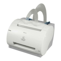
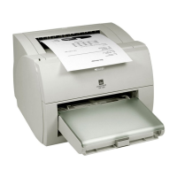
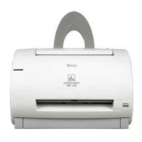
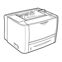
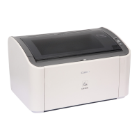
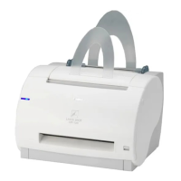
Identifies and illustrates external and internal printer components.
Guides correct installation and site requirements.
Provides guidelines for storing and handling the EP-22 toner cartridge.
Lists routine maintenance tasks for the end-user.
Explains printer operation and advanced printing technology.
Divides printer functions into five main groups: video, engine, image, laser/scanner, pickup/feed.
Details the printer's operational sequence from power-on to printing completion.
Explains the step-by-step process when the printer is powered on.
Details the engine controller PCB and its functions in managing printer operations.
Describes temperature control and safety mechanisms for the fixing unit.
Explains how high voltages are generated and applied to printer components.
Details AC to DC voltage conversion for printer operation.
Describes signals exchanged between interface and engine controllers.
Explains laser diode, scanning mirror, and their role in image formation.
Details modes and signals for laser diode emission control.
Explains scanner motor control and synchronization with the laser beam.
Covers creating a visible image from toner on the photosensitive drum.
Details the five major stages of image formation, from charging to cleaning.
Describes how paper is picked up from trays and fed into the printer.
Explains how the printer detects and identifies paper jams.
Explains interface controller's role in receiving and processing print data.
Introduces disassembly/reassembly procedures and safety precautions for service.
Details removal of external covers like rear, right, left, upper, and cartridge covers.
Covers removal of major internal components like laser/scanner and drive assemblies.
Identifies and describes key parts like pickup rollers, separation pads, and charging rollers.
Shows arrangement and function of various switches, sensors, and indicator LEDs.
Details location and function of main motor and pick-up solenoid.
Illustrates location of interface, engine, and display PCBs within the printer.
Introduces malfunction diagnosis and troubleshooting procedures.
Explains how to perform engine and controller test prints to diagnose issues.
Provides solutions for image quality issues like light, dark, or distorted prints.
Guides on identifying and resolving paper jam issues.
Addresses problems related to paper feeding, wrinkles, and skewing.
Covers troubleshooting for issues like no AC power or no DC power.
Helps diagnose and resolve status errors like laser/BD or fixing unit failures.
Details procedures for checking nip width and other technical measurements.
Outlines cleaning procedures during service visits and lists standard tools.
Shows location of various connectors on printer PCBs.
Provides timing chart for printing two A4-size sheets continuously.
Presents schematic circuit diagram of the engine controller PCB.
Details signals for various connectors on the engine controller PCB.
Describes printer status and error messages displayed on the computer screen.
| Print Technology | Laser |
|---|---|
| Print Resolution | 600 x 600 dpi |
| Paper Capacity | 150 sheets |
| Paper Capacity (A4) | 150 sheets |
| Interface | USB |
| Supported OS | Windows 98/Me/2000/XP |