Do you have a question about the Canon LBP-CX Series and is the answer not in the manual?
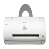
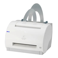
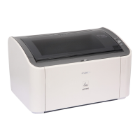
Describes the printer's non-impact, electrophotography-based design, high-quality prints, and compact size.
Details the printer's technical specifications, including type, printing method, speed, and power consumption.
Covers laser safety standards, CDRH regulations, and additional safety precautions for servicing.
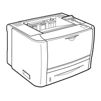
Identifies external and internal parts of the printer through diagrams and labels.
Explains the printer's display unit, test switch, print density adjustment, and operating procedures.
Outlines the printer's functional division into system interface, laser scanner, and print unit.
Details the semiconductor laser principles and the scanning mirror mechanism for image exposure.
Describes the electrophotographic process, image formation system, and printing sequences.
Explains handshaking signals and video signal processing for external device communication.
Provides an overview of the printer's electrical system and component control via microcomputer.
Lists electrical components, their symbols, functions, and PCB layouts for reference.
Details the printer's operational sequences (PURS, WAIT, INTR, PRINT, LSTR, STBY, PAUSE).
Explains the electrical aspects of the laser and scanner unit, including control signals.
Presents block diagrams for key circuits like DC controller, power supplies, and drivers.
Details the AC and DC power supply circuits, including interlock and voltage regulation.
Illustrates signal timing for the DC controller during various printer operations.
Describes the removal of external covers and panels for access to printer components.
Explains the main motor and its role in driving printer components for operation.
Details the paper feeding mechanisms, including manual feed, cassette pickup, and transport guides.
Covers the laser and scanner unit, including removal, installation, and beam-blocking shutter.
Describes the EP cartridge, including photosensitive drum, corona assembly, and cleaning.
Explains the fixing assembly, including rollers, heater, and nip width measurement.
Details the removal and layout of various PCBs and electrical components within the printer.
Provides recommendations for printer placement, environmental conditions, and space requirements.
Guides through the printer unpacking process, component checks, and initial setup procedures.
Offers advice on proper storage conditions and handling techniques for EP cartridges.
Lists consumables and their expected service life in terms of print count.
Provides a comprehensive list of tools required for servicing the printer.
Details recommended lubricants and cleaning agents for printer maintenance.
Outlines critical checkpoints for servicing and cleaning various printer components.
Describes maintenance tasks that can be performed by the end-user, such as replacing consumables.
Provides initial checks and basic procedures for diagnosing printer problems.
Explains how to use the printer driver and laser driver checker for electrical and mechanical adjustments.
Illustrates common image defects and provides tables for identifying causes and solutions.
Details troubleshooting steps for specific printer malfunctions, including power and motor issues.
Addresses issues related to paper jams and incomplete feeding in various transport areas.
Diagrams showing the location of major printer assemblies and units.
Presents a general circuit diagram for the 115V/60Hz model, illustrating interconnections.
Provides wiring diagrams detailing electrical connections for the 115V/60Hz model.
Details the DC controller PCB, including connector locations and signal lists.
Illustrates the circuit diagram for the high-voltage power supply system.
Shows the circuit diagrams for the DC power supply and main motor driver.
Presents circuit diagrams for the AC driver, AC controller, and fixing roller heater safety PCBs.
Provides circuit diagrams for varistor, preconditioning exposure lamps, and print counter.
Illustrates the physical layout of the Expansion RAM PCB for the A2 model.
Shows the physical layout of the DC Controller PCB, including component placement.
Illustrates the physical layout of the DC Power Supply and Main Motor Driver PCB.
Shows the physical layout of the AC Controller and Fixing Roller Heater Safety PCBs.
Depicts the physical layout of the Varistor PCB.
Illustrates the physical layout of the Preconditioning Exposure Lamps and Print Counter PCB.
Presents the second part of the Expansion RAM PCB circuit diagram.
Shows the location and types of warning labels on the printer.